Imaging optical system

a technology of optical system and optical plate, applied in the field of imaging optical plate, can solve the problems of image quality degradation and achieve the effects of satisfactory suppression of reflection factor, satisfactory mass productivity, and convenient handling

Inactive Publication Date: 2009-10-15
PANASONIC CORP
View PDF12 Cites 20 Cited by
  • Summary
  • Abstract
  • Description
  • Claims
  • Application Information

AI Technical Summary

Benefits of technology

[0017]According to the present invention, an imaging optical system is realized in which the reflection factor is satisfactorily suppressed on an optical surface while handling is easy and satisfactory mass productivity is obtained.

Problems solved by technology

This causes a problem that reflected light is generated and causes image quality degradation such as ghost and flare near the periphery of the optical surface where suppression of the reflection factor is insufficient.

Method used


Image

  • Imaging optical system
  • Imaging optical system
  • Imaging optical system

Examples


embodiment 1

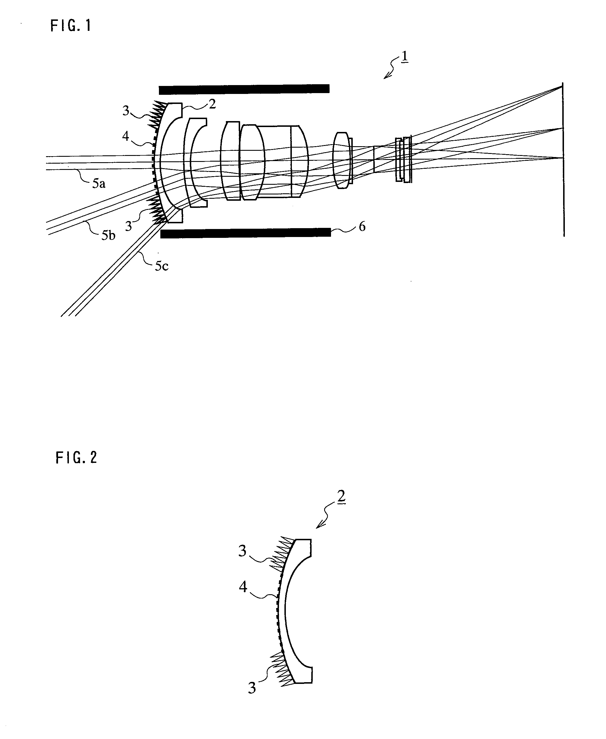
[0043]FIG. 1 is a schematic sectional view showing a configuration of an imaging optical system 1 according to Embodiment 1. FIG. 1 shows an example of an imaging optical system suitable for wide-angle image taking in which the focal length does not vary. The imaging optical system 1 is held by a lens barrel 6. Light beams 5a, 5b and 5c are light beams that pass through the imaging optical system 1. The light beam 5c is a light beam that passes at the maximum view angle of the imaging optical system 1.

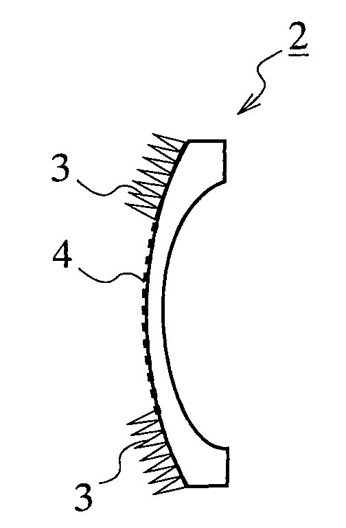
[0044]FIG. 2 is an enlarged view of a lens element 2 located on the most object side among the lens elements employed in the imaging optical system 1 shown in FIG. 1. In FIG. 2, the lens element 2 has an antireflection structure 3 in at least part of a peripheral region (simply referred to as a “peripheral region”, hereinafter) located in the periphery of a center region (simply referred to as a “center region”, hereinafter) containing the center (the vicinity of the center) of the obj...

embodiment 2

[0092]In Embodiment 1, an antireflection multilayer film is formed in the center region of the lens element located on the most object side, while an antireflection structure is formed in the peripheral region. Here, the antireflection multilayer film may be formed such as to cover the entire surface of the lens element, and then the antireflection structure may be formed thereon.

[0093]The basic configuration of an imaging optical system according to the present Embodiment 2 is similar to that of the imaging optical system according to Embodiment 1. Thus, FIG. 1 is to be referred to concerning the configuration of the imaging optical system. Here, the lens element 2 in FIG. 1 is replaced by a lens element 12 shown in the following FIG. 10 in the present Embodiment 2.

[0094]FIG. 10 is an enlarged view of a lens element 12 employed in an imaging optical system according to Embodiment 2. In FIG. 10, an antireflection multilayer film 14 is formed such as to cover the entire surface of th...

embodiment 3

[0097]The basic configuration of an imaging optical system according to the present Embodiment 3 is similar to that of the imaging optical system according to Embodiment 1. However, in the lens element located on the most object side, the configuration of an antireflection structure provided in at least part of the peripheral region of the object side optical surface is different from the configuration of the antireflection structure in Embodiment 1.

[0098]FIG. 11 is an enlarged sectional part view of a lens element 22 employed in an imaging optical system according to Embodiment 3. The lens element 22 corresponds to the lens element 2 shown in FIG. 1, and is the lens element located on the most object side in the imaging optical system 1 of FIG. 1. As shown in FIG. 11, a sheet 25 having an antireflection structure 23 is stuck in at least part of the peripheral region of a substrate 24 that constitutes the lens element 22 and is composed of, for example, a material capable of absorbi...


PUM

PropertyMeasurementUnit
wavelengthaaaaaaaaaa

Abstract

An imaging optical system according to the present invention is provided with at least one lens element and comprises: an optical surface through which incident light transmits; and an antireflection structure provided in at least part of a peripheral region located in the periphery of a center region containing the center of an optical surface in one or more optical surfaces, wherein the peripheral region is within an optical effective diameter, and wherein the antireflection structure is a structure in which structural units having a predetermined shape are arranged periodically in the form of an array at a period smaller than a minimum wavelength of light whose reflection should be prevented in the incident light.

Description

RELATED APPLICATIONS[0001]This application is the U.S. National Phase under 35 U.S.C. § 371 of International Application No. PCT / JP2006 / 315510, filed on Aug. 4, 2006, which in turn claims the benefit of Japanese Application No. 2005-229161, filed on Aug. 8, 2005, the disclosure of which Applications are incorporated by reference herein.TECHNICAL FIELD[0002]The present invention relates to an imaging optical system. In particular, the present invention relates to an imaging optical system in which the reflection factor is suppressed on an optical surface while handling is easy and satisfactory mass productivity is obtained. The imaging optical system is suitably applicable to various imaging devices such as digital cameras.BACKGROUND ART[0003]In recent years, the size of the digital camera market is in an increasing trend. In general, the digital camera market is roughly divided into a market where cameras of high magnification and high resolution are targeted and a market where comp...

Claims


Application Information

Patent Timeline
Patent Type & Authority Applications(United States)
IPC IPC(8): G02B1/11G02B1/02G02B1/115G02B1/118G02B13/00
CPCG02B1/11G02B1/118G02B5/045G02B3/0056G02B5/001G02B3/0006
Inventor OKAYAMA, HIROAKIYOSHIKAWA, MOTONOBUYOSHITSUGU, KEIKIYAMAMOTO, YOSHIHARU
Owner PANASONIC CORP
Why Eureka
Try Eureka