Microphone Screen With Common Mode Interference Reduction

Inactive Publication Date: 2009-10-15
PLANTRONICS
View PDF5 Cites 36 Cited by
  • Summary
  • Abstract
  • Description
  • Claims
  • Application Information

AI Technical Summary

Problems solved by technology

In telecommunication systems, the phone handset or headset microphone is susceptible to common mode interference, such as power line interference noise signals or other electromagnetic radiation detected as noise or interference.
However, the PCB metal traces forming the copper layers still do not typically provide a contiguous grounded copper shield due to normal gaps between traces.
Since this acoustic port and the PCB output

Method used


Image

  • Microphone Screen With Common Mode Interference Reduction
  • Microphone Screen With Common Mode Interference Reduction
  • Microphone Screen With Common Mode Interference Reduction

Examples


Embodiment Construction

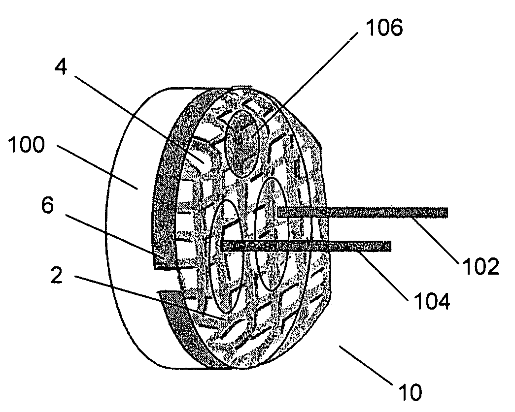
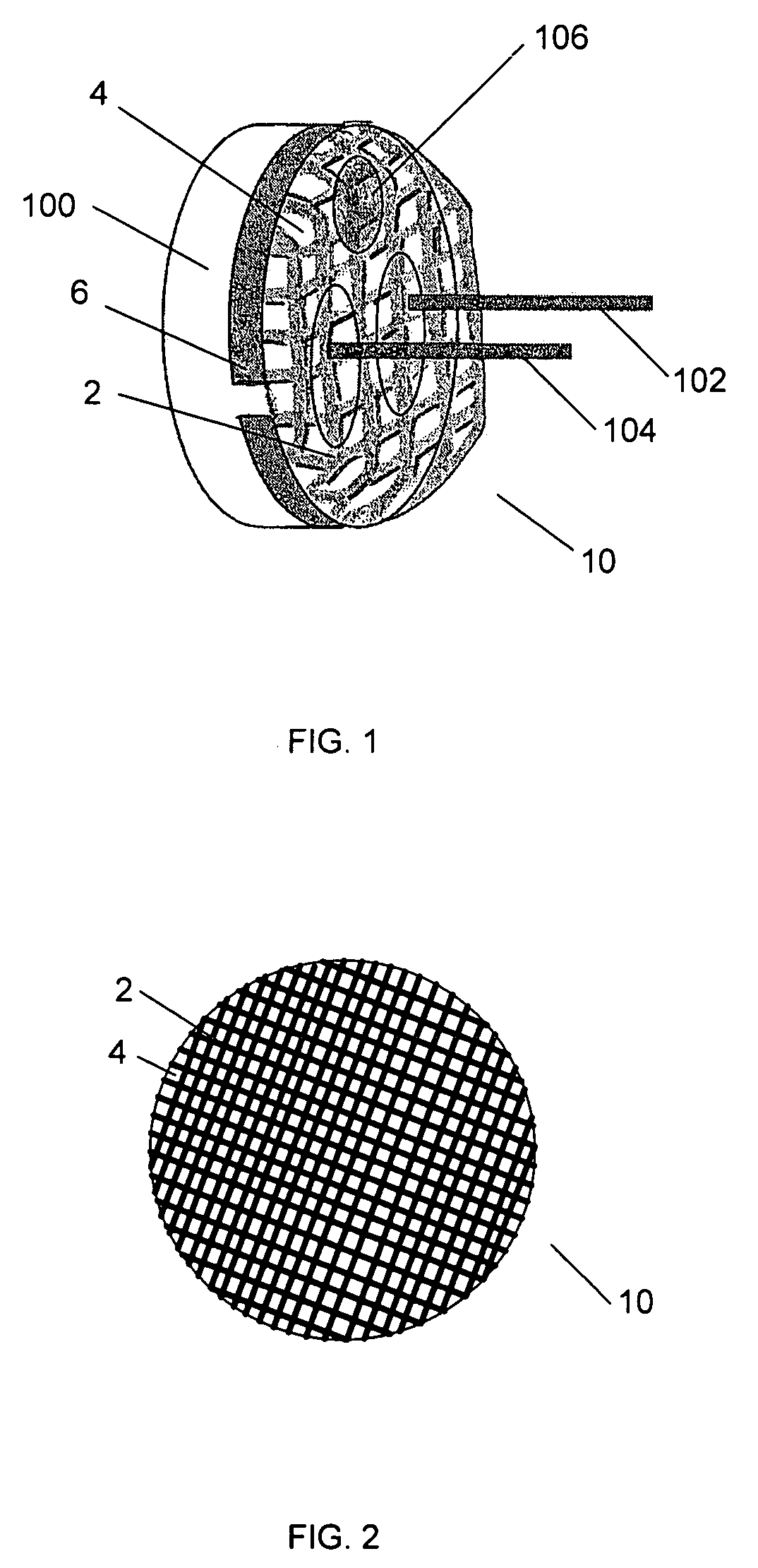
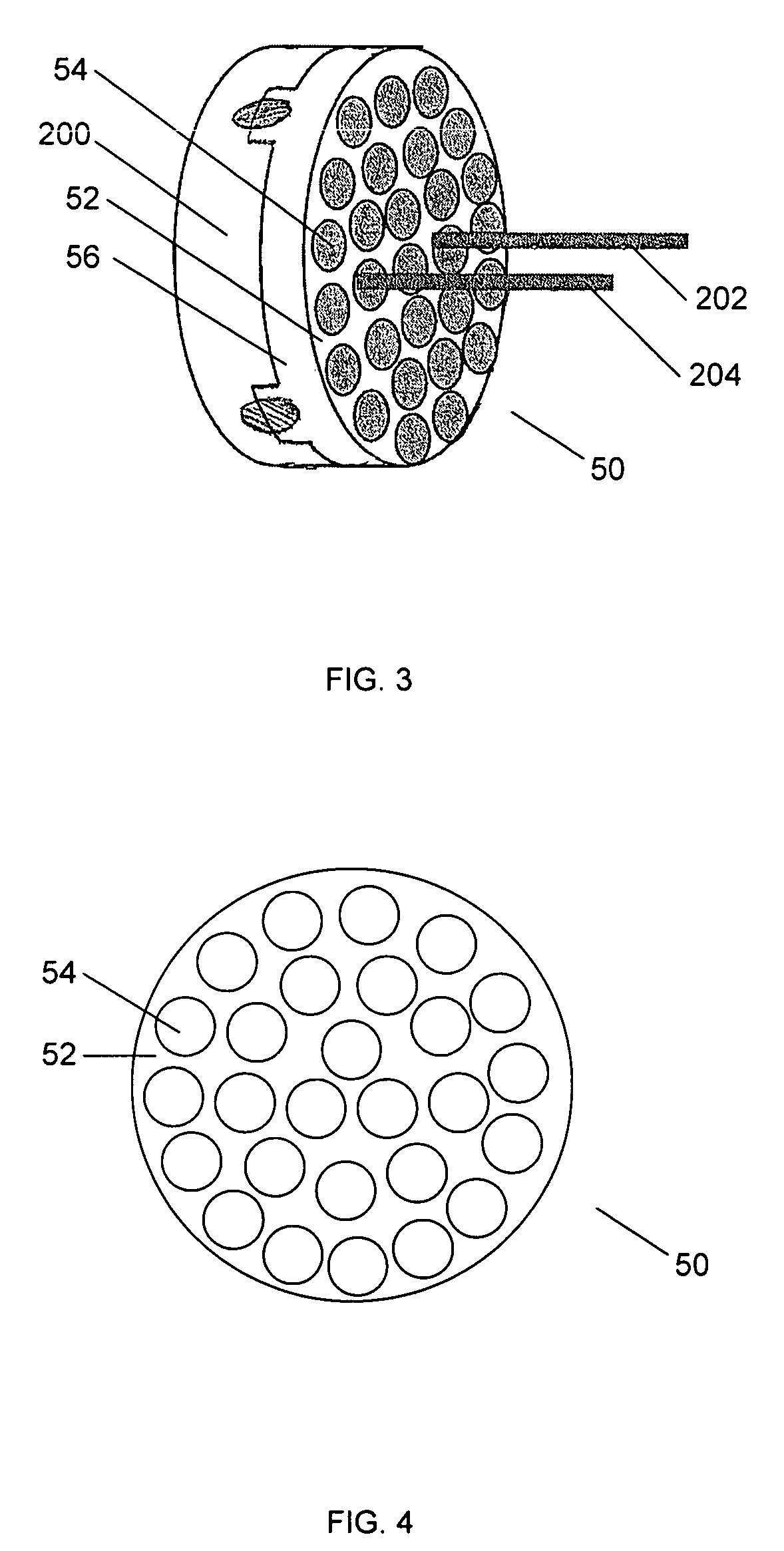
[0020]Methods and apparatuses for microphone assemblies are disclosed. The following description is presented to enable any person skilled in the art to make and use the invention. Descriptions of specific embodiments and applications are provided only as examples and various modifications will be readily apparent to those skilled in the art. The general principles defined herein may be applied to other embodiments and applications without departing from the spirit and scope of the invention. Thus, the present invention is to be accorded the widest scope encompassing numerous alternatives, modifications and equivalents consistent with the principles and features disclosed herein. For purpose of clarity, details relating to technical material that is known in the technical fields related to the invention have not been described in detail so as not to unnecessarily obscure the present invention.

[0021]Generally, this description describes a method and apparatus for a microphone assembl...


PUM


Abstract

A microphone assembly includes a microphone composed of a case having an open end and a printed circuit board. The printed circuit board is disposed in the open case end. The microphone assembly further includes a metal screen coupled to the case over the printed circuit board for shielding the microphone from electromagnetic interference. The metal screen includes several apertures.

Description

BACKGROUND OF THE INVENTION[0001]In telecommunication systems, the phone handset or headset microphone is susceptible to common mode interference, such as power line interference noise signals or other electromagnetic radiation detected as noise or interference. This interference is commonly referred to as buzz and hum noise. The noise signals are fundamentally at 50-60 Hz and can also be associated with higher order frequency harmonics.[0002]In the prior art, microphones use a metal enclosure to provide a measure of shielding from buzz and hum noise. Typically, the shielding is partially accomplished by mounting the microphone element in a cylindrical metal case or “can”. The back of a noise canceling microphone is typically a printed circuit board (PCB) having two layers of copper. The conductive case provides shielding from the sides, but does not shield the back of the microphone. In the prior art, careful PCB design to obtain maximum ground (at zero voltage reference) coverage ...

Claims


Application Information

Patent Timeline
IPC IPC(8): H04R19/04
CPCH04R1/04H04R1/086
Inventor KHAMASHTA, ROBERT M.SHYU, CHINGFISH, DENNIS S.
Owner PLANTRONICS
Why Eureka
Try Eureka