Antigen exposure chamber system

an exposure chamber and antigen technology, applied in the field of antigen exposure chamber systems, can solve the problems of large loss of antigen particles, inability to measure, and extremely non-uniform distribution of antigen concentration in the chamber of each of them, and achieve the effect of accurately measuring an antigen concentration and minimizing the flow

Active Publication Date: 2009-10-15
SHINRYOI CORP
View PDF2 Cites 5 Cited by
  • Summary
  • Abstract
  • Description
  • Claims
  • Application Information

AI Technical Summary

Benefits of technology

[0015]As a result of employing the above configuration, the antigen exposure chamber system according to the present invention is capable of uniformizing the antigen concentrations in the chamber with a variation of around ±10%.
[0016]Furthermore, it is capable of minimizing the flow of the antigen in the chamber to the outside, and also capable of accurately measuring an antigen concentration within the chamber.

Problems solved by technology

However, each of them has an extremely non-uniform antigen concentration distribution in the chamber (for example, see Non-Patent Document 1).
Furthermore, there are no measures to prevent an antigen from flowing out of the chamber more than making the chamber pressure to be a negative pressure, which is extremely insufficient for preventing an antigen from flowing out of the chamber, so there has been the possibility that an antigen flows to the outside of the antigen exposure chamber.
However, there are various kinds of materials for sampling tubes for the conventional antigen exposure chamber systems, and there are no fixed arrangement routes for such sampling tubes, and compensation of the measured values has not been made.
Accordingly, there is a problem in that the loss of antigen particles is so large that an accurate concentration measurement cannot be conducted, depending on the material, the length or the bent portion count of the tube.Patent Document 1: NoneNon-Patent Document 1: N. Krug et al., Validation of an environmental exposure unit for controlled human inhalation studies with grass pollen in patients seasonal allergic rhinitis, Clinical & Experimental Allergy, Vol. 33, No. 12, p.p.

Method used


Image

  • Antigen exposure chamber system
  • Antigen exposure chamber system
  • Antigen exposure chamber system

Examples


Embodiment Construction

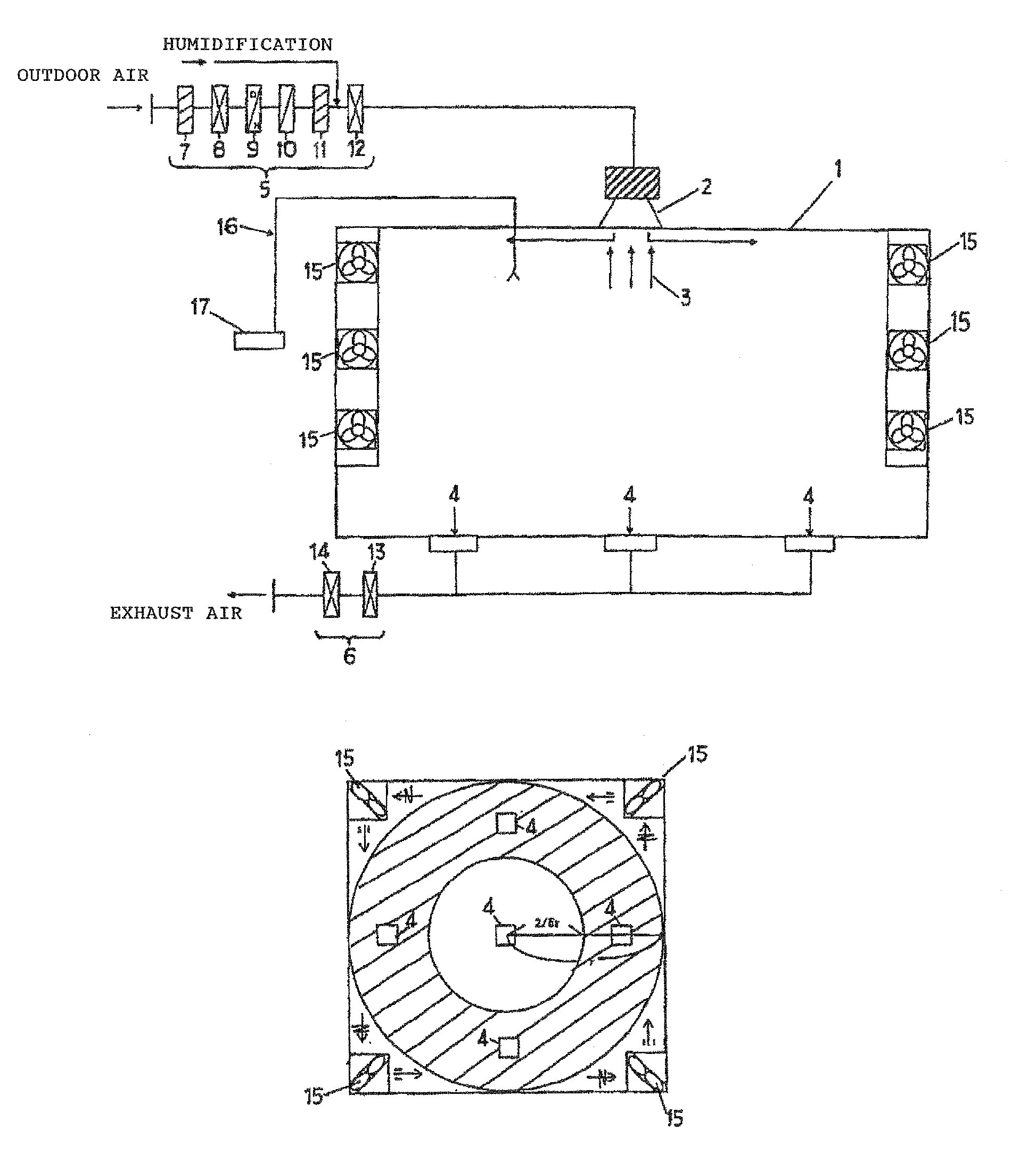
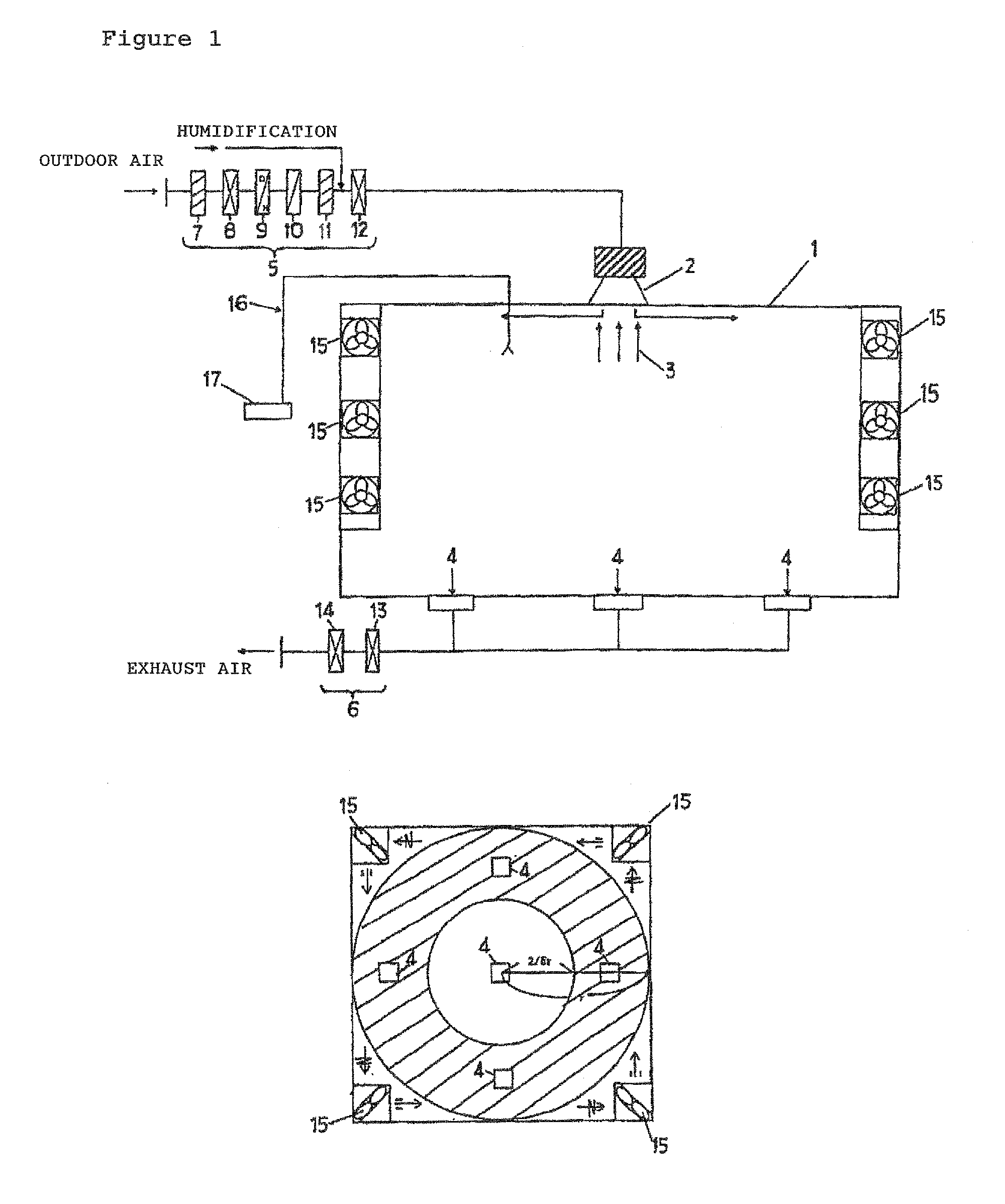
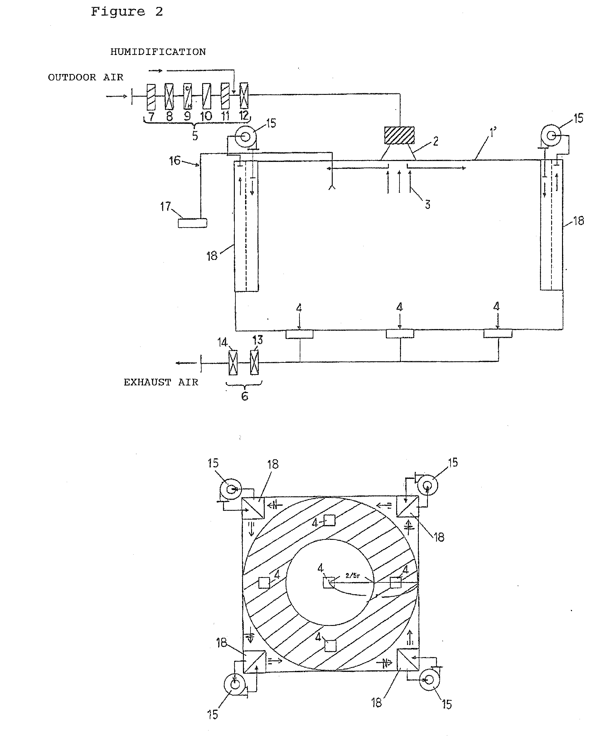
[0032]FIG. 1 shows a side view and plain view of a schematic configuration of an embodiment of an antigen exposure chamber system according to the present invention. Generally, an antigen exposure chamber 1 is configured so as to blow a certain high concentration antigen 3, such as pollen, mite or house dust, etc., supplied from an antigen supply device (not shown) into an outdoor air supplied from an outdoor air diffuser 2 provided at the center of its ceiling to mix them, and to make the air containing the thus mixed antigen permeate the chamber, and to exhaust the air from air exhaust ports 4 provided at the floor surface of the antigen exposure chamber.

[0033]The outdoor air to be supplied to the outdoor air diffuser 2 is supplied via a supply air filter unit 5. The supply air filter unit 5 includes a pre-air filter 7, a medium-efficiency air filter 8, a cold / hot water coil 9, a pre-heater 10, an activated carbon filter 11 and a HEPA (high-efficiency particulate air) filter 12.

[0...


PUM

PropertyMeasurementUnit
diameteraaaaaaaaaa
concentrationaaaaaaaaaa
pressureaaaaaaaaaa

Abstract

An object of the present invention is to solve the problems in conventional art antigen exposure chambers, and specifically, to provide an antigen exposure chamber system capable of simultaneously exposing a large number of test objects in a chamber to a uniform antigen (pollen, mite or house dust, etc.) in all seasons. In order to achieve the above object, in an antigen exposure chamber system according to the present invention, an outdoor air is supplied via an outdoor air diffuser 2 provided in a ceiling surface of an exposure chamber 1 into the exposure chamber from the ceiling surface of the exposure chamber in a horizontal direction, a fan unit 15, including a supply port and a suction port, is provided in each of the four corners of the exposure chamber to provide a circulating flow of air flowing with circulation in the horizontal direction in the exposure chamber, an air exhaust port 4 is provided at a floor surface of the exposure chamber to exhaust an air from the floor surface of the exposure chamber, an antigen is supplied from an antigen supply device to the outdoor air diffuser provided on the ceiling surface so that the antigen is mixed with the outdoor air, and a uniform concentration antigen exposure is enabled by the circulating flow of air.

Description

TECHNICAL FIELD[0001]The present invention relates to an antigen exposure chamber system for exposing test objects to an antigen.BACKGROUND ART[0002]Antigen exposure chamber systems configured so as to supply a predetermined amount of antigen to expose test objects to the antigen have been used for experiments and researches relating to diseases such as allergy.[0003]Conventional antigen exposure chamber systems include ones provided with a ceiling air supply port and a ceiling air exhaust port at the ceiling of the chamber, or an air supply port at the ceiling of the chamber and an air exhaust port at the lower portion of the chamber walls, thereby generating an air flow flowing between the air supply port and the air exhaust port and mixing an antigen supplied from the outside of the chamber into this air flow. However, each of them has an extremely non-uniform antigen concentration distribution in the chamber (for example, see Non-Patent Document 1).[0004]Furthermore, there are n...

Claims


Application Information

Patent Timeline
Patent Type & Authority Applications(United States)
IPC IPC(8): G01N33/00B01J19/00
CPCA61G10/00A61G10/02A62B11/00G01N33/53
Inventor TANG, HUAIPENGSETA, AKIHIROANAI, TOSHIHIROUEDA, TOSHIKATSUOKUDA, MINORUHASHIGUCCI, KAZUHIROOKUBO, KIMIHIRO
Owner SHINRYOI CORP
Why Eureka
Try Eureka