
Polishing system having a track

a polishing system and track technology, applied in the direction of lapping machines, grinding heads, ways, etc., can solve the problems of remaining difficult to achieve high throughput and flexibility to meet process requirements in a polishing system

Inactive Publication Date: 2009-10-15
APPLIED MATERIALS INC
View PDF14 Cites 28 Cited by
  • Summary
  • Abstract
  • Description
  • Claims
  • Application Information

AI Technical Summary

Benefits of technology

[0021]Embodiments described herein further provide a replaceable seal device that is easily removed or installed from a circular track system with minimal system downtime.
[0023]In yet another embodiment, the replaceable seal comprises a seal member coupled to two or more backing plates. In one embodiment, the seal member may be coupled with the backing plate by molding the seal member on the backing plate. The seal member comprises an inner circumferential face forming a recessed portion for accommodating the rail of a track assembly. The backing plate is made such that it provides rigidity to the seal member while allowing the replaceable seal assembly to be removed or installed without compromising the seal assembly.
[0024]In yet another embodiment, the replaceable seal is fixed to an end portion of a guide block which is fixed to an end portion of a slider of the guide block to prevent foreign objects such as dirt and dust from entering the guide block and slider, the slider straddling a rail of a circular track.
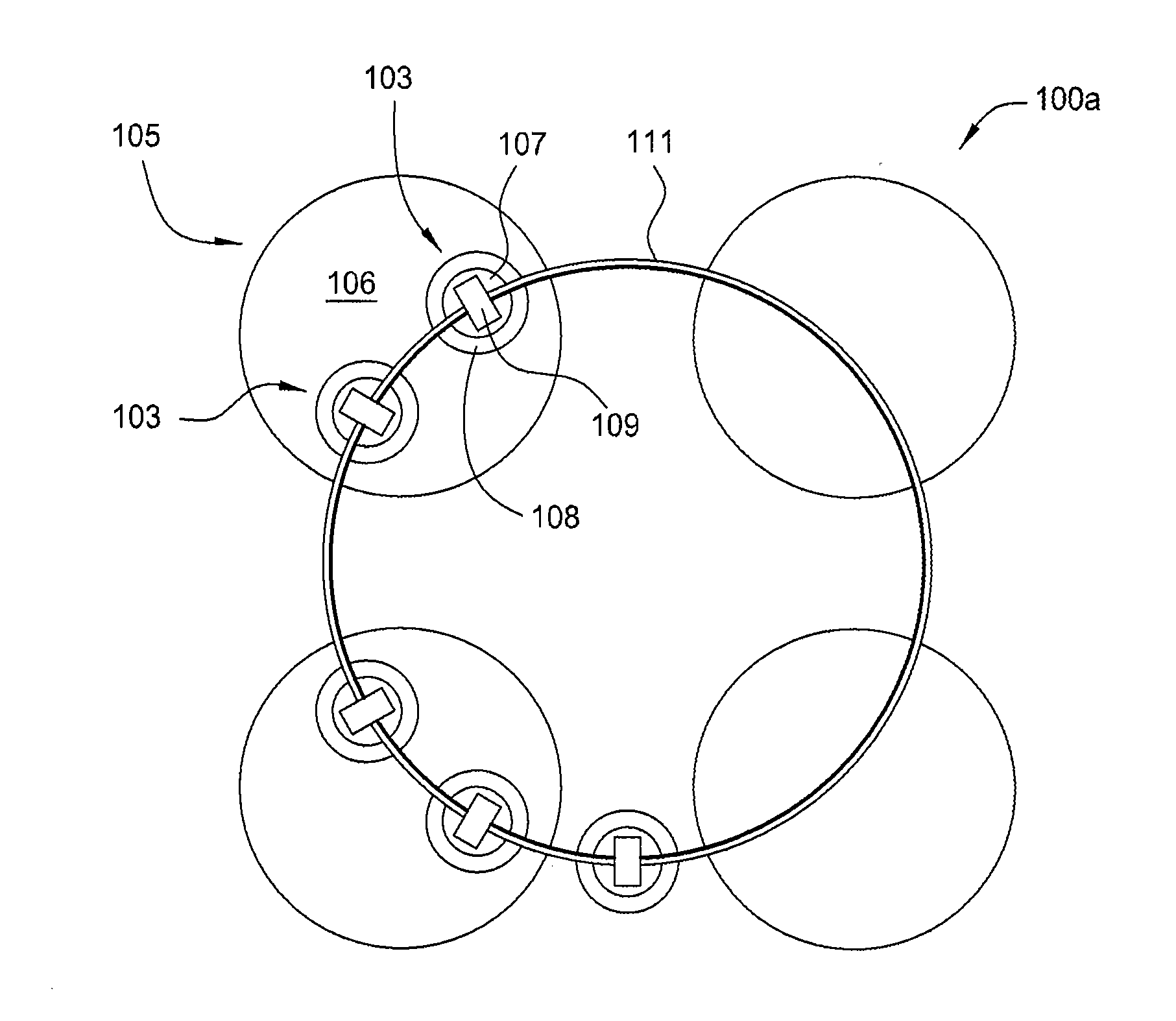
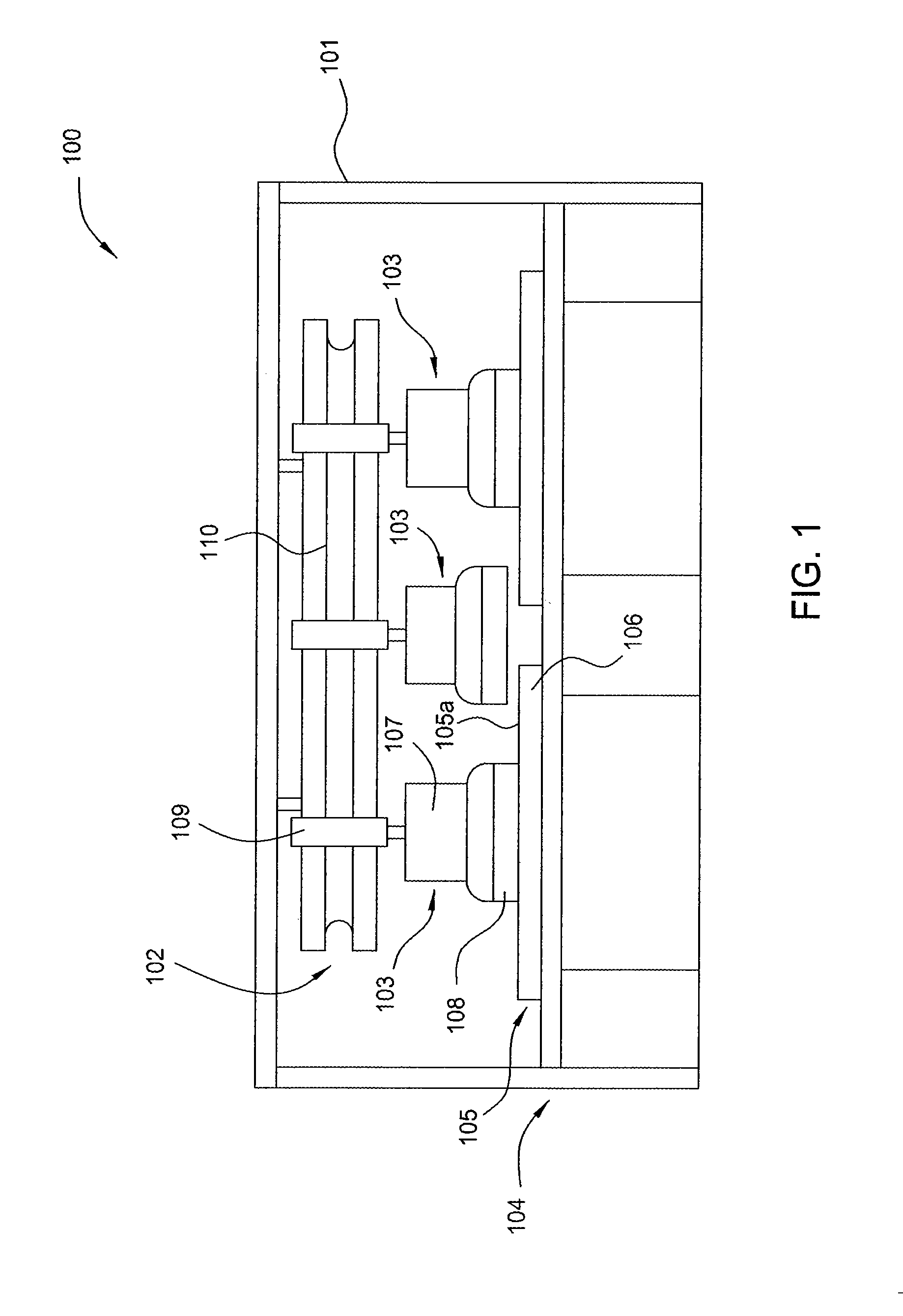
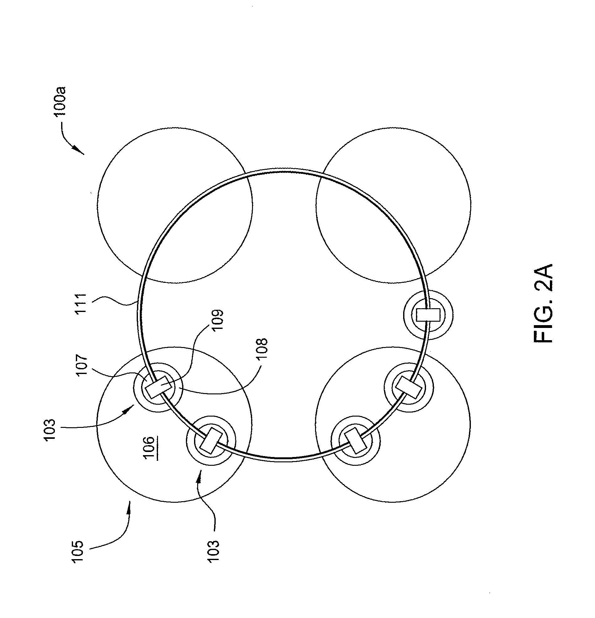
[0026]In yet another embodiment, a circular track system configured to transfer polishing heads in a polishing system is provided. The circular track system comprises a supporting frame, a track coupled to the supporting frame and defining a path along which the polishing heads are configured to move, and one or more carriages configured to carry at least one polishing head along the path defined by the track, wherein the track comprises a guide rail and each of the one or more carriages comprises one or more guide blocks with a replaceable seal which movably couple each respective carriage to the guide rail and restrict movements of the respective carriage within the path.

Problems solved by technology

However, it remains challenging to achieve high throughput and flexibility to meet process requirements in a polishing system.

Method used


Image

  • Polishing system having a track
  • Polishing system having a track
  • Polishing system having a track

Examples


Embodiment Construction

[0078]Embodiments described herein relate to an apparatus and a method for transferring and supporting a substrate in a chemical mechanical polishing (CMP) system or electrochemical mechanical polishing (ECMP) system. In one embodiment described herein, a track system is used to transfer one or more polishing heads independently among polishing stations, loading / unloading station, and / or cleaning stations. In one embodiment, the track system comprises a stator strip defining a path along which one or more polishing heads may be moved by interactions between a rotor in each of the one or more polishing heads and the stator strip. In one embodiment, the stator strip comprises a plurality of permanent magnets, the rotor is a segment motor, and the polishing head is moved or stopped by interaction between magnetic fields of the permanent magnets and magnetic fields generated by the segment motor from electronic power provided to the segment motor. In one embodiment, one or more guide ra...


PUM

PropertyMeasurementUnit
movementsaaaaaaaaaa
diameteraaaaaaaaaa
curvatureaaaaaaaaaa

Abstract

Embodiments described herein relate to a track system in a polishing system. One embodiment described herein provides a track system configured to transfer polishing heads in a polishing system. The track system comprises a supporting frame, a track coupled to the supporting frame and defining a path along which the polishing heads are configured to move, and one or more carriages configured to carry at least one polishing head along the path defined by the track, wherein the one or more carriages are coupled to the track and independently movable along the track.

Description

CROSS-REFERENCE TO RELATED APPLICATIONS[0001]This application claims benefit of U.S. Provisional Patent Application Ser. No. 61 / 043,582, filed Apr. 9, 2008, U.S. Provisional Patent Application Ser. No. 61 / 043,600, filed Apr. 9, 2008, U.S. Provisional Patent Application Ser. No. 61 / 056,384, filed May 27, 2008, U.S. Provisional Patent Application Ser. No. 61 / 056,256, filed May 27, 2008, U.S. Provisional Patent Application Ser. No. 61 / 087,124, filed Aug. 7, 2008, and U.S. Provisional Patent Application Ser. No. 61 / 087,127, filed Aug. 7, 2008, all of which are herein incorporated by reference in their entirety.BACKGROUND[0002]1. Field[0003]Embodiments described herein relate to an apparatus and a method for processing semiconductor substrates. More particularly, embodiments described herein provide apparatus and methods for transferring and actuating polishing heads during polishing.[0004]2. Description of the Related Art[0005]Sub-micron multi-level metallization is one of the key techn...

Claims


Application Information

Patent Timeline
Patent Type & Authority Applications(United States)
IPC IPC(8): B24B1/00B24B7/20B24B41/02E01B25/24B24B37/04
CPCB24B37/04B24B45/003B24B41/047
Inventor YILMAZ, ALPAYD'AMBRA, ALLEN L.RANGARAJAN, JAGANKARUPPIAH, LAKSHMANAN
Owner APPLIED MATERIALS INC
Learn More