Generator for prosthesis and orthosis

Inactive Publication Date: 2009-10-15
ANDRYSEK JAN
View PDF7 Cites 17 Cited by
  • Summary
  • Abstract
  • Description
  • Claims
  • Application Information

AI Technical Summary

Benefits of technology

[0008]In accordance with one aspect of the present invention there is provided an artificial knee joint with a means to generate electrical current from the motions (activities) of the prosthesis or orthosis during walking, jogging or running For convenience, an electromechanical generator such as a DC motor is applied to a knee joint, so that relative motions between the tipper (thigh) and lower (shank) portions of the knee joint will drive the motor rotor. A transmission means, such as a gear assembly, is used to amplify the motions at the knee joint. in order to increase the rotor speed, and facilitate the generation of adequate levels of current. This electrical current may be used to recharge onboard batteries, or directly to power the electronics of a microprocessor-based prosthesis, by way of example only and therefore eliminating the need for a battery pack.
[0009]The other aspect of the invention relates to the use of the generator namely a geared motor to provide damping. By decreasing the electrical resistance between the motor terminals, generated current is allowed to flow back into the geared motor. This increases the resistance in the motor, in effect causing the motor through the transmission to act as a damper.

Problems solved by technology

However, if the amputee significantly alters his / her walking pattern, the knees will require further adjustment on the part of the prosthetist.
Furthermore, fluid-based dampers tend to be complex and susceptible to leaks.
One drawback of these technologies is that the user must charge the on-board batteries on a daily basis.
A second drawback is that the systems tend to be heavy and bulky, in part due to the battery packs.

Method used


Image

  • Generator for prosthesis and orthosis
  • Generator for prosthesis and orthosis
  • Generator for prosthesis and orthosis

Examples


Embodiment Construction

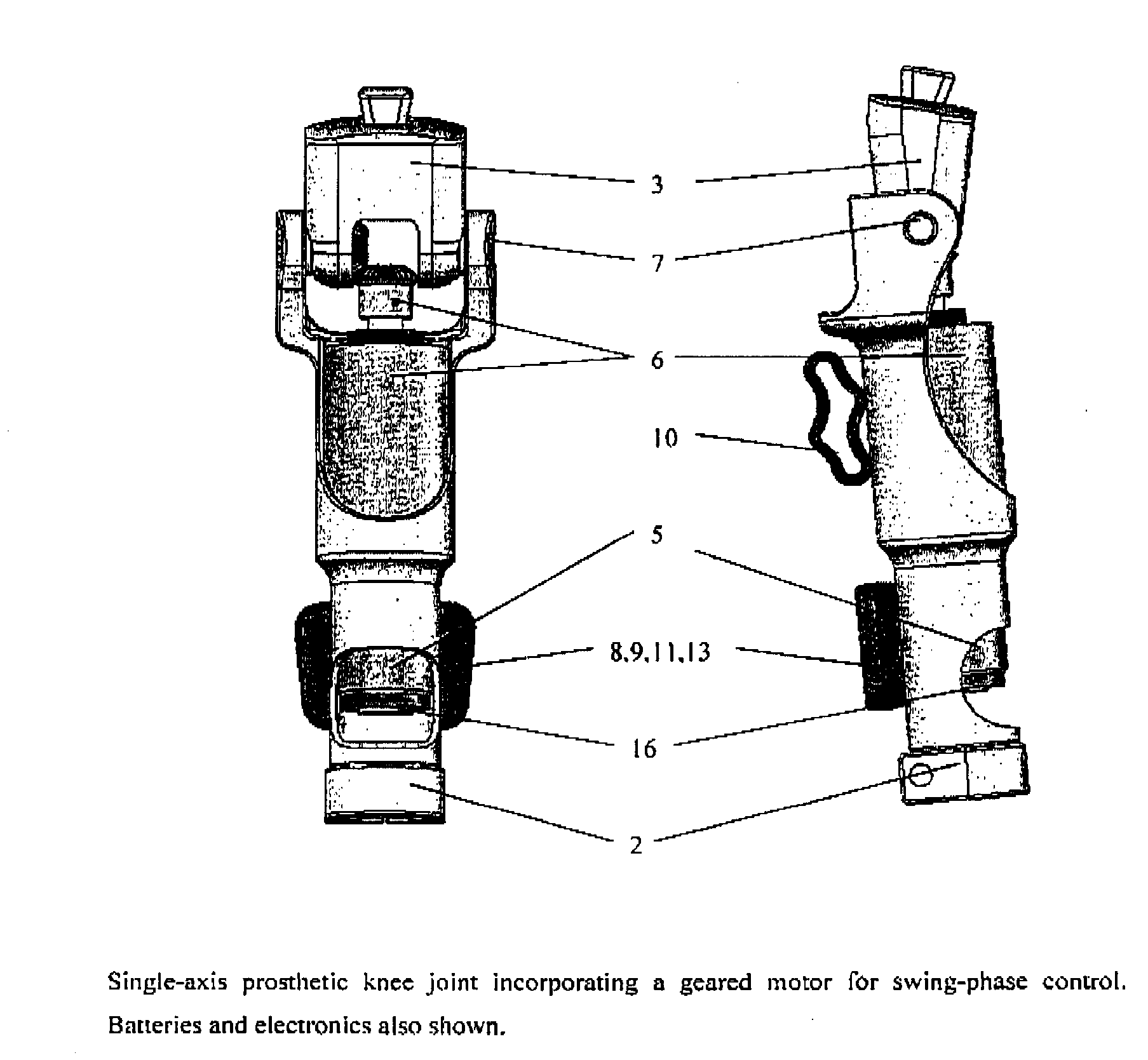
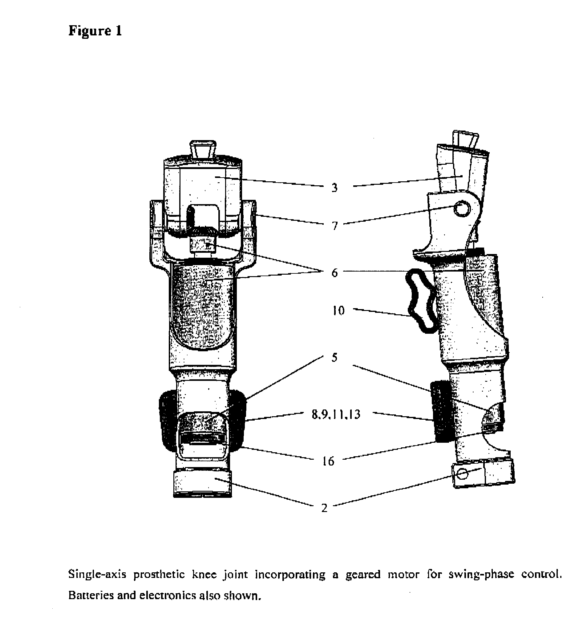
[0023]The following description relates to the preferred embodiments of the present invention for a generator in a prosthetic or orthotic joint. In accordance with a preferred embodiment of the present invention there is provided a generator for a prosthesis having a means for generating electrical current using body energy transmitted to the prosthesis. Body energy may be further defined as energy emanating from activities from the body such as mechanical, vibrational, psychological, thermal, ultrasonic (sound waves via muscles), or biochemical body energy, current by way of example only, that is then transmitted to the prosthesis and converted into an electrical current. The mode of transmission of the body energy to the prosthesis may vary depending an the type of body energy being generated. For example, mechanical body energy may be generated and transmitted by the movement of the body or through a force being exerted within the body.

[0024]The means for generating electrical cu...


PUM


Abstract

A means for using body energy to generate electrical current to power the electronics, sensors, actuators and other electronic components in microprocessor-controlled prosthetic or orthotic joints. Furthermore, a means for using the generator to provide swing-phase damping is disclosed whereby the damping level can be controlled and adjusted electronically.

Description

FIELD OF INVENTION [0001]This invention relates generally to a power generating method and system that uses body energy from gait to operate electronic prosthetic or orthotic devices.BACKGROUND OF INVENTION[0002]Artificial joints generally require mechanisms to control their movement. For example an artificial knee joint or prosthetic joint will be prescribed for a person with a through-knee (TK) or an above-knee (AK) amputation. i.e. a person without a knee joint, shank or foot. The ability for the knee to bend or articulate during sitting, kneeling or ambulating is desirable. It is also desirable to have the ability to control the leg during the swing and stance-phases of gait when the person is walking or running.[0003]The “swing-phase control” refers to the control of the joint's movement or articulation during the swing-phase of the gait cycle to make the gait more efficient and more natural looking. Traditionally fluid-based pneumatic or hydraulic dampers are used in prostheti...

Claims


Application Information

Patent Timeline
IPC IPC(8): A61F2/70
CPCA61F2/64H02N2/18A61F2/76A61F2002/30527A61F2002/5006A61F2002/701A61F2002/704A61F2002/705A61F2002/745A61F2002/747A61F2002/7625A61F2002/768A61F2220/0025A61F2310/00005H02K7/1853A61F2/68A61F2/70A61F2002/30523A61F2/74
Inventor ANDRYSEK, JAN
Owner ANDRYSEK JAN
Why Eureka
Try Eureka