
Method and Apparatus for Stimulating Wells with Propellants

a technology of propellant and well, applied in the direction of fluid removal, borehole/well accessories, weapons, etc., can solve the problems of extending the fracture regime, destroying and rubbing formation, and limiting the success of early methods, so as to achieve and extend the fractures. the effect of multiple fracture regimes

Active Publication Date: 2009-10-22
DALE B SEEKFORD
View PDF31 Cites 6 Cited by
  • Summary
  • Abstract
  • Description
  • Claims
  • Application Information

AI Technical Summary

Benefits of technology

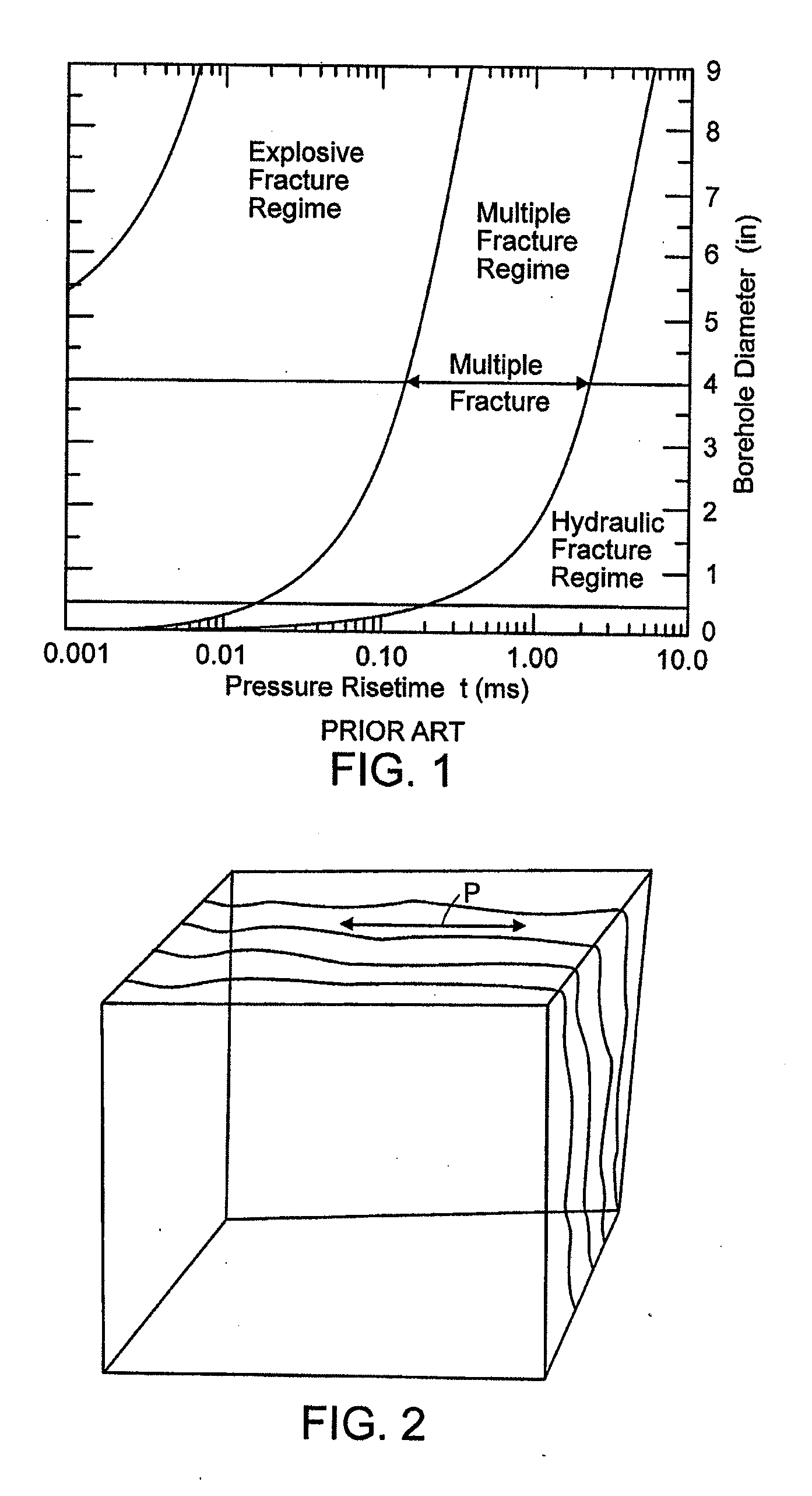
[0017]The present invention achieves these objectives by using an internal propellant ignition system that is predictable and repeatable, in combination with a propellant that has the characteristics needed to enable the multiple fracture regime to be reached and extended. The propellant uses a long burn time in combination with a predetermined pressure rise time to provide the energy needed to create and / or extend the fractures.
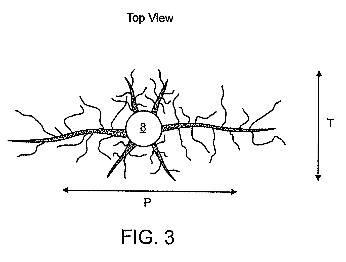
[0018]The present invention also creates multiple fractures in the multiple fracture zone and extends them further into the formation. This is achieved using an enhanced (rapid) critical pressure rise time and sufficient peak pressure, in combination with the extended propellant burn time. After the fractures are initiated, they can be extended into the formation by gas that is still being generated by the propellant.
[0021]Another aspect of the invention features an explosive transfer cap for transferring an ignition from an upper propellant firing train to a lower propellant firing train within a producing or injection well. The explosive transfer cap includes a housing that has a first seal, a second seal, and a longitudinal axis extending therethrough. An explosive charge is between the first and second seals, to facilitate ignition along the longitudinal axis. Although the propellant units are referred to as “upper” and “lower”, other configurations can also be used. For example, horizontal and sloped arrangements work effectively with all aspects of the invention.
[0030]Yet another aspect of the invention features a method of controlling stimulation gas flow to a producing or injection well. This includes the steps of sizing a propellant charge of a propellant unit to correspond to a total desired stimulating gas volume or amount to be generated, igniting the propellant charge within the well using a detonating member disposed within the propellant unit, and splitting the propellant a number of times corresponding to the amount of initial gas pressure to be established. Preferably, the splitting of the propellant charge is along a longitudinal axis of the propellant charge. This can result in a plurality of substantially symmetrical propellant charge fragments, to effectively achieve a predetermined combustion gas generation rate.

Problems solved by technology

These early methods had only limited success.
Frequently, the explosive fracture regime causes formation damage and rubblization, damaging and sealing off some of the pore space.
This results in an undesirable loss of porosity.
Each of these techniques has issues with wellbore conditions, explosive propellants, and / or minimal effective stimulation due to lack of or loss of energy.
This type of ignition makes it difficult to predictably reproduce the event.
This does not allow for a predictable, consistent amount of propellant surface area to be ignited.
The propellant of Snider is broken into a random number of pieces, resulting in unpredictable pressure rise and propellant flow results.
Much of the energy required for formation treatment is lost to the well fluid that inhibits the burn.
Hill '943 and '951 uses a compressible fracturing fluid to carry the propant into the fractures, causing hydraulic fracturing due to the energy stored in the “compressible” fluid.
The restricted flow area can be caused by the overburden exerting excessive compression on the formation near the wellbore, or by man-made damage near the wellbore, e.g., during drilling operations.
For example, fluids or materials introduced into the wellbore can restrict permeability, reducing fluid communication and decreasing flow capacity to the pay zone.
Certain wells have pay zones that cannot be effectively produced without some type of stimulation.
Unfortunately, they each possess certain limitations.
For example, none of them utilize a predictable internal ignition system to enable them to reach a critical pressure rise time necessary to enter into the multiple fracture regime and to provide sufficient gas volume to be able to extend the multiple fractures sufficiently far into the formation while protecting the propellant from the fluid in the wellbore.

Method used


Image

  • Method and Apparatus for Stimulating Wells with Propellants
  • Method and Apparatus for Stimulating Wells with Propellants
  • Method and Apparatus for Stimulating Wells with Propellants

Examples


Embodiment Construction

[0048]The invention relates to apparatus and methods to stimulate subterranean wells, including injection or production wells, utilizing rocket propellants. Wells such as oil and gas production wells can be stimulated to enhance oil or gas production. Although the following discussion focuses on oil production wells, the technology is also applicable to gas production wells, injection wells, storage wells, brine or water production wells, disposal wells, and the like. Known stimulation techniques can include multiple fracturing and / or cleaning near the wellbore to reduce flow interference that can be caused by debris. As described above, hydraulic fracturing processes create fluid (e.g., gas and / or liquid) communication by fracturing the rock with hydraulic pressure. A propping material can also be used, such as sand, bauxite, or other materials which are designed to keep the fracture open to an extensive area of the pay zone. But hydraulic fracturing is not efficient or practicable...


PUM


Abstract

The present invention relates to apparatus and methods to stimulate subterranean production and injection wells, such as oil and gas wells, utilizing rocket propellants. Rapid production of high-pressure gas from controlled combustion of a propellant, during initial ignition and subsequent combustion, together with proper positioning of the energy source in relation to geologic formations, can be used to establish and maintain increased formation porosity and flow conditions with respect to the pay zone.

Description

RELATED APPLICATIONS[0001]This application claims priority to and benefit of U.S. Ser. No. 60 / 655,456, filed Feb. 23, 2005, the contents of which are incorporated herein by reference.FIELD OF THE INVENTION[0002]The present invention relates to apparatus and methods to stimulate subterranean wells, including injection or production wells, utilizing rocket propellants. Wells such as oil and gas production wells can be stimulated to enhance oil or gas production.BACKGROUND[0003]Early attempts to increase fluid flow area around the wellbore of a subterranean production well, such as an oil and / or gas production well, used devices and materials such as nitroglycerin, dynamite, or other such high energy materials to produce an explosive event that would create flow area at desired locations. These early methods had only limited success. A presentation of Cuderman's work at the Society of Petroleum Engineers (SPE) conference in Pittsburgh, Pa. on May 16-18, 1982, confirmed the existence of...

Claims


Application Information

Patent Timeline
Patent Type & Authority Applications(United States)
IPC IPC(8): E21B43/263
CPCE21B43/263F42B3/02F42B3/28F42B3/24F42B3/22
Inventor SEEKFORD, DALE B.
Owner DALE B SEEKFORD
Learn More