Heating cooker

Active Publication Date: 2009-10-22
PANASONIC CORP
View PDF4 Cites 26 Cited by
  • Summary
  • Abstract
  • Description
  • Claims
  • Application Information

AI Technical Summary

Benefits of technology

[0019]When the operation-unit illuminators emit light, the key indicators illuminate and appear in the top plate to allow a user to easily identify their functions and accurate positions of the electrostatic touch keys. The key indicators can be invisible to the user upon the operation-unit illuminators not emitting light. For example, when the electrostatic touch keys are inoperable, the operation-unit illuminators do not emit light so as to allow the user to select only the illuminating electrostatic touch keys, thereby preventing the user from erroneously operating the cooker.
[0020]The illumination controller may change the illumination state of the operation-unit illuminators every time the cooker is operated. For example, the controller may change the illumination state of the indicators provided on the electrodes according to the current validity, order of priority, and other conditions of the electrostatic touch keys. The user presses the top plate at an illuminating key indicator whil

Problems solved by technology

However, the alarm may confuse the user to remind the user of information (e.g.

Method used


Image

  • Heating cooker
  • Heating cooker
  • Heating cooker

Examples


exemplary embodiment 1

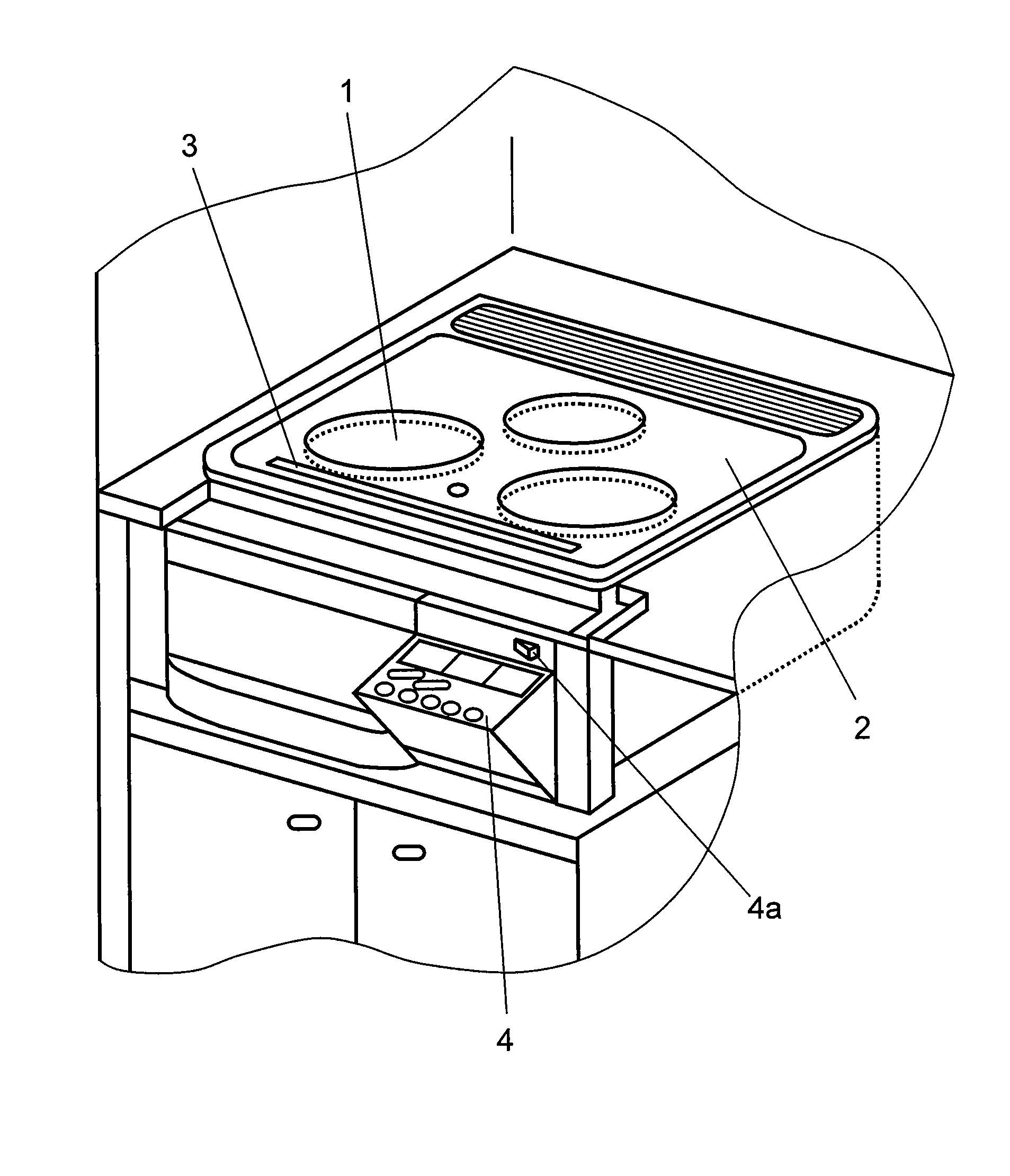
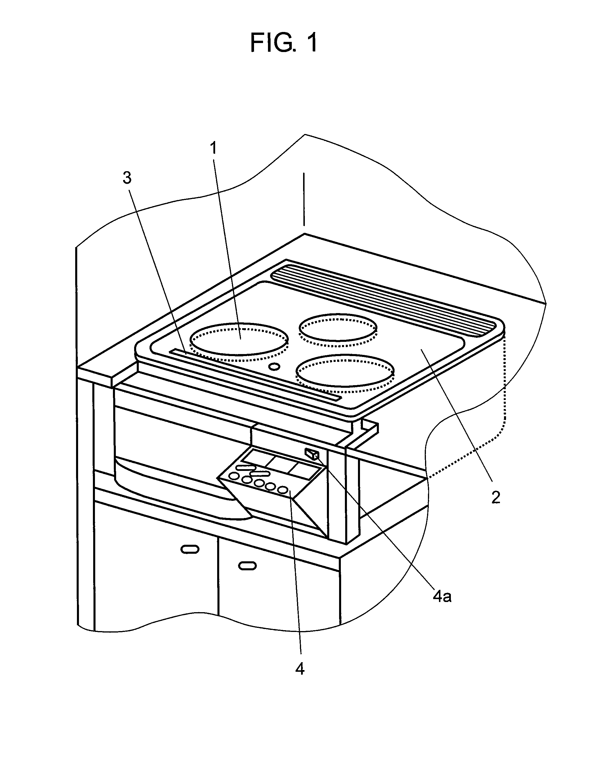
[0070]FIG. 1 is a perspective view of a heating cooker according to exemplary Embodiment 1 of the present invention.

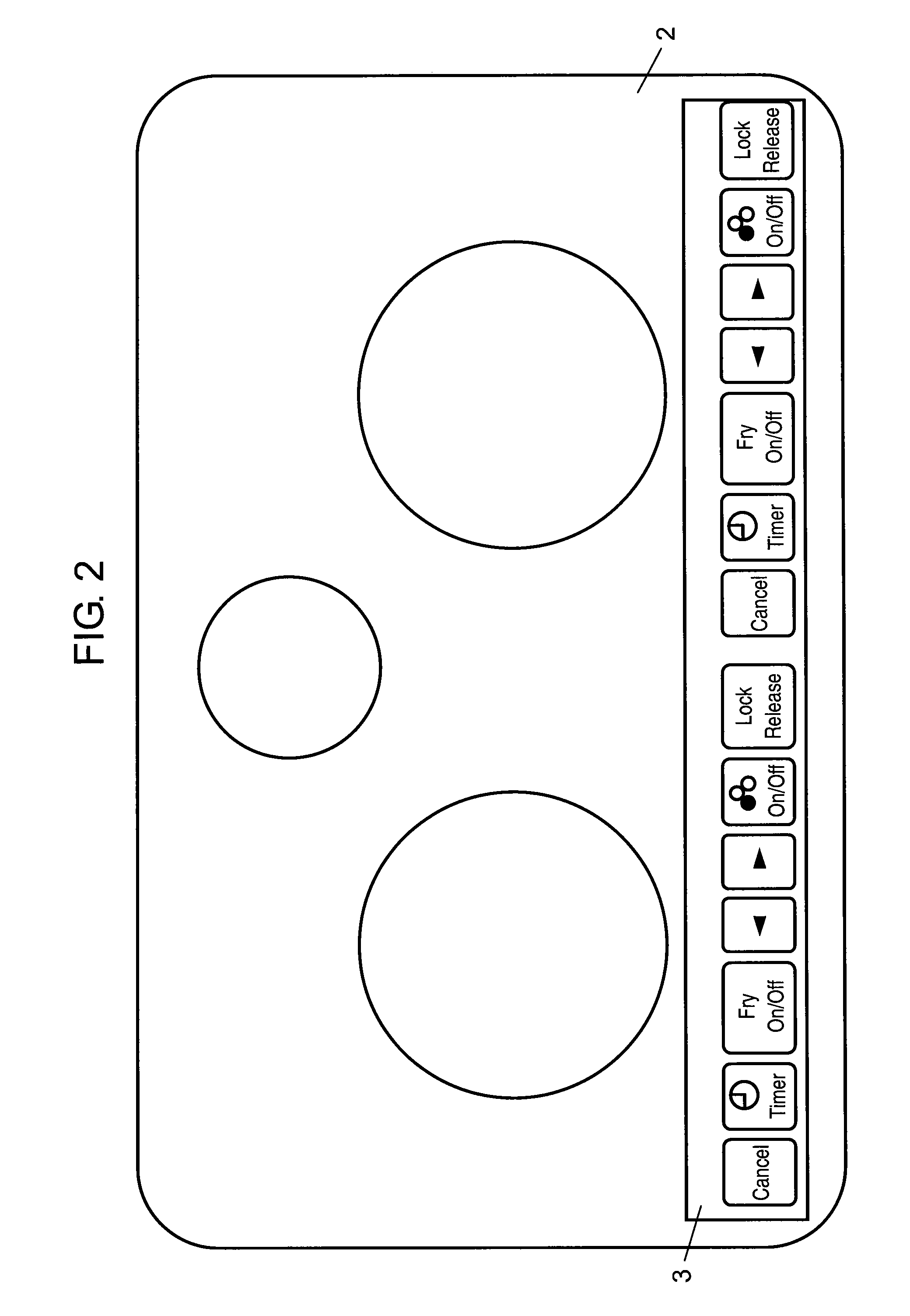
[0071]In FIG. 1, this heating cooker essentially includes top plate 2 provided on an upper surface of the heating cooker and arranged to have an object (not shown) to be placed thereon, heater unit 1 indicated by a circular pattern printed with film on a lower surface of top plate 2, top-panel operation unit 3 formed on top plate 2 in front of heater unit 1, and kangaroo-type operation unit 4 retractable on a front surface of the heating cooker. Top plate 2 has a plate shape and made of insulating material, such as heat-resistant glass of crystallized ceramic, having high heat resistance and light-transmittance. An induction heating coil (not shown) generating a high-frequency magnetic field is provided below heater unit 1 in the cooker, and faces heater unit 1. At least top-panel operation unit 3 on top plate 2 is colored in black, and the other portions of top plate ...

exemplary embodiment 2

[0095]An appearance and essential structure of a heating cooker according to Exemplary Embodiment 2 of the invention are similar to those of the heating cooker shown in FIGS. 1 to 3, and their detailed descriptions will be omitted.

[0096]FIG. 6A is a top view of top-panel operation unit 3 of a heating cooker according to exemplary Embodiment 2 while all light-guiding panels 7 emit light at a second brightness, a predetermined low brightness. FIG. 6B is a top view of top-panel operation unit 3 while one light-guiding panel 7 emits light at a first brightness, a predetermined high brightness higher than the second brightness. FIG. 6C is a top view of top-panel operation unit 3 while two light-guiding panels 7 emit light at the first brightness, the predetermined high brightness. Each of electrostatic touch keys 11aa to 11gg show electrostatic touch key 5 corresponding to each function.

[0097]In particular, electrostatic touch key 11gg is a lock release key (referred to as “lock release ...

exemplary embodiment 3

[0102]An appearance and essential structure of a heating cooker according to Exemplary Embodiment 3 of the invention are similar to those of the heating cooker shown in FIGS. 1 to 3, and their detailed descriptions will be omitted.

[0103]FIG. 7 is a block diagram of an operation unit of the heating cooker according to Embodiment 3 of the invention.

[0104]As shown in FIG. 7, the operation unit essentially includes memory 12 storing operation procedures of the heating cooker, sound generator 13, electrostatic touch key 14 having electrode 14b pressed by finger 14a, and guidance operation selector 15.

[0105]Electrostatic touch key 14 forms a capacitor between finger 14a and electrode 14b. Electrode 14b is provided on a surface of top plate 2 opposite to a surface of top plate 2 arranged to have an object (not shown) placed thereon, namely, on the lower surface of top plate 2. Finger 14a touching the surface arranged to have the object (not shown) placed thereon. A high-frequency voltage i...


PUM


Abstract

An appliance including a top plate has its operability improved and prevents an operation error. The appliance includes electrostatic touch keys provided on a lower surface of the top plate, the electrostatic touch keys including electrodes made of conductive films having predetermined light-blocking property, respectively, operation-unit illuminators emitting light toward the electrodes, which are partially cut, from a direction opposite to the top plate, respectively, and an illumination controller controlling illumination of the operation-unit illuminators. The illumination controller changes the illumination state of the shapes of key indicators above the electrodes to allow a user to identify function and validity of the electrostatic touch keys. The illumination controller controls the illumination state of operation-unit illuminators, such as lighting-on, blinking, lighting-off, and adjusting the brightness, to provide information required for operation.

Description

TECHNICAL FIELD[0001]The present invention relates to a heating cooker having an operation guidance function.BACKGROUND ART[0002]FIG. 9 is a block diagram of conventional electronic appliance 100 having an operation guidance function. Electronic appliance 100 includes data bus 101. Memory 102 is connected to data bus 101, stores operation guidance corresponding to a specification of electronic appliance 100. The operation guidance is produced by previously determining operation procedures of electronic appliance 100.[0003]Memory 102 includes a read-only memory (ROM). Indicator 103 is connected to memory 102 via data bus 101, and displays the operation guidance read from memory 102. In this case, the operation guidance includes a series of operation procedures having a hierarchical structure to perform predetermined functions. Indicator 103 includes a liquid crystal display (LCD).[0004]Selector 104 is connected to indicator 103 via data bus 101, and is operated by a user to select a ...

Claims


Application Information

Patent Timeline
IPC IPC(8): H05B3/02H01H9/00
CPCF24C7/082H03K17/9622H05B2213/03H03K2217/96046H03K2217/96042
Inventor ISODA, KEIKONAGATA, RYUUJISATOU, CHIKASHIINADA, TSUYOSHI
Owner PANASONIC CORP
Why Eureka
Try Eureka