Method and system for operating a wind energy installation

a technology for wind energy installations and wind power generators, applied in the direction of machines/engines, electric generator control, final product manufacture, etc., can solve the problem of difficult to precisely measure the wind speed, and achieve the effect of reducing the rotation speed and maximizing the energy yield

Active Publication Date: 2009-10-22
SIEMENS GAMESA RENEWABLE ENERGY SERVICE GMBH
View PDF7 Cites 41 Cited by
  • Summary
  • Abstract
  • Description
  • Claims
  • Application Information

AI Technical Summary

Benefits of technology

[0014]In particular, the invention makes it possible to record the total load on a wind energy installation very accurately in the particularly critical region of the rated wind speed, that is to say the wind speed at which the wind energy installation actually reaches the rated power, and to operate it with a severe oblique incident flow in such a way that impermissible loads are safely avoided, while at the same time, however, maximizing the energy yield, that is to say in particular in the region of the rated wind speed, the wind energy installation can be operated close to its permissible load limits. This was not possible with the already known methods.
[0015]In one simple case of the method according to the invention, the load value is made equal to 0 when the measured value (for example the rotor rotation speed) on which the load value is based is below a predetermined value (for example half the rated rotation speed), and the load value is made equal to 1 when the measured value is above the predetermined value. The oblique incident flow value is correspondingly equal to 0 when the measured value (for example the angle betwe...

Problems solved by technology

However, in practice, it is diffi...

Method used


Image

  • Method and system for operating a wind energy installation
  • Method and system for operating a wind energy installation
  • Method and system for operating a wind energy installation

Examples


Embodiment Construction

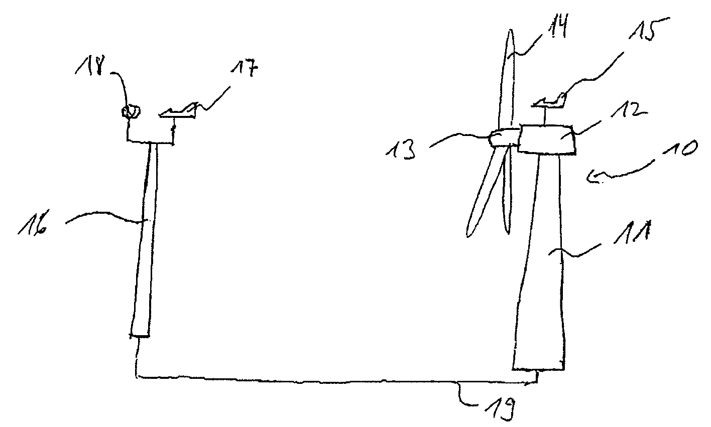
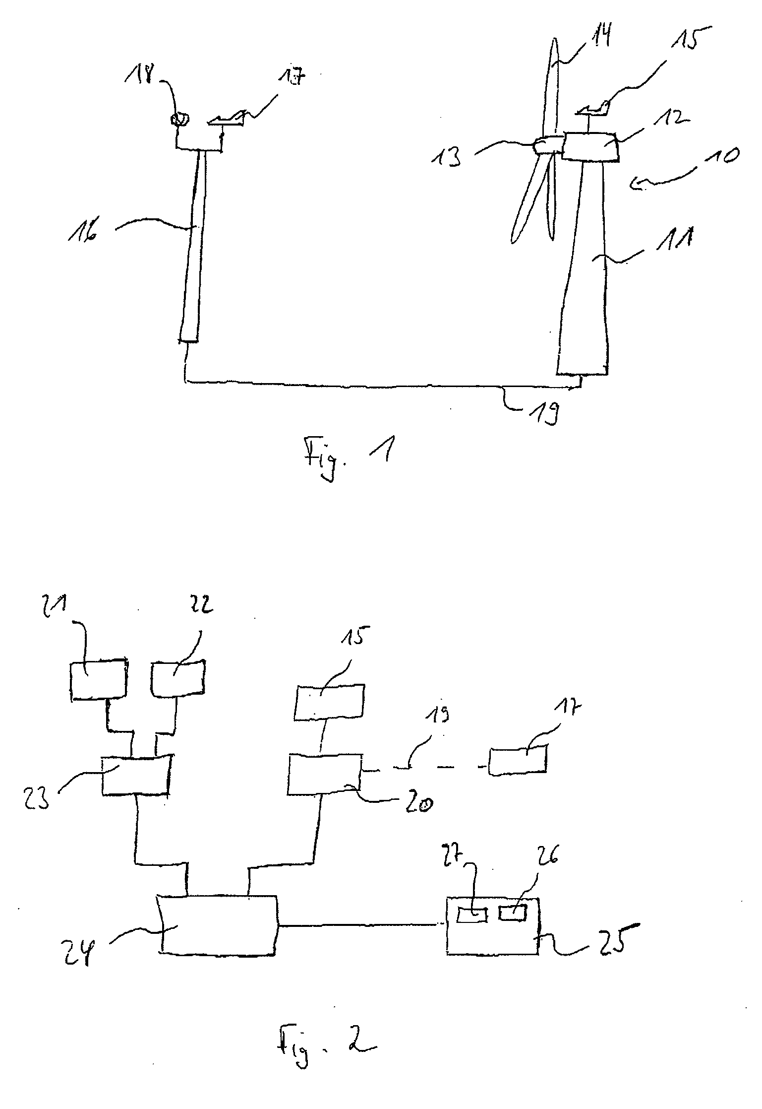
[0035]A wind energy installation 10 in FIG. 1 comprises a pod 12 which is arranged on a tower 11 and has a rotor 13. The rotor 13 comprises three rotor blades 14 whose pitch is variable, in order to control the rotation speed of the rotor 13. A wind direction gauge in the form of a wind vane 15, possibly as well as a wind strength gauge, which is not illustrated, in the form of an anemometer, are or is fitted to the pod 12.

[0036]A mast 16 is erected in front of the wind energy installation 10, and a further wind vane 17 and wind strength gauge 18 are arranged at the top of this mast 16. The measured values of the wind direction gauge 17 and of the wind strength gauge 18 are recorded and are transmitted via a cable 19 to the wind energy installation 10. As an alternative to the measurement mast, it is also possible to use ground-based appliances which can measure the wind speed at the hub height (for example Lidar or Sodar).

[0037]According to FIG. 2, an evaluation unit 20 is arranged...


PUM


Abstract

A method for operating a wind energy installation and a system for implementing the method. An oblique incident flow value, which represents the difference between the wind direction and the direction of a rotor axis of the wind energy installation, and a load value, which represents the load state of the wind energy installation, are determined. A total load value is determined based on the load value and the oblique incident flow value. The rotor rotation speed is reduced when the total load value is above a first limit value. The wind energy installation is shut down when, in addition, a second limit value is exceeded. The method makes it possible to react objectively to oblique incident flows and can reduce a load on a wind energy installation without causing large yield losses.

Description

REFERENCE TO RELATED APPLICATIONS[0001]This application claims the priority of German Patent Application No. 10 2008 020 154.5, filed Apr. 22, 2008, the contents of which are incorporated herein by reference.FIELD OF THE INVENTION[0002]The invention relates to a method for operation of a wind energy installation. In the method, an oblique incident flow value is determined which represents the difference between the wind direction and the direction of the rotor axis of the wind energy installation. If the oblique incident flow value exceeds a predetermined limit value, then the rotor rotation speed of the wind energy installation is reduced. The invention also relates to an arrangement for carrying out the method. The arrangement comprises a wind energy installation and a wind direction gauge, with a control unit being provided, which reduces the rotor rotation speed of the wind energy installation when the oblique incident flow detected by the wind direction gauge exceeds a predeter...

Claims


Application Information

Patent Timeline
IPC IPC(8): H02P9/04
CPCF03D7/0224F03D7/0264F03D7/0276F03D7/042F05B2260/80Y02E10/723F05B2270/20F05B2270/321F05B2270/329F05B2270/331F05B2270/335F05B2270/101Y02E10/72Y02P70/50
Inventor VON MUTIUS, MARTINWEITKAMP, ROLANDANEMUELLER, JOCHEN
Owner SIEMENS GAMESA RENEWABLE ENERGY SERVICE GMBH
Why Eureka
Try Eureka