
Resistive module, voltage divider and related layout methods

a resistive module and voltage divider technology, applied in the field of resistive modules, voltage dividers, etc., can solve the problems of increased layout area, increased cost due to variable resistor implementation, and degrade the display quality of lcd, so as to achieve precise resistive values and increase the cost and layout area

Inactive Publication Date: 2009-10-22
CHUNGHWA PICTURE TUBES LTD
View PDF6 Cites 3 Cited by
  • Summary
  • Abstract
  • Description
  • Claims
  • Application Information

AI Technical Summary

Benefits of technology

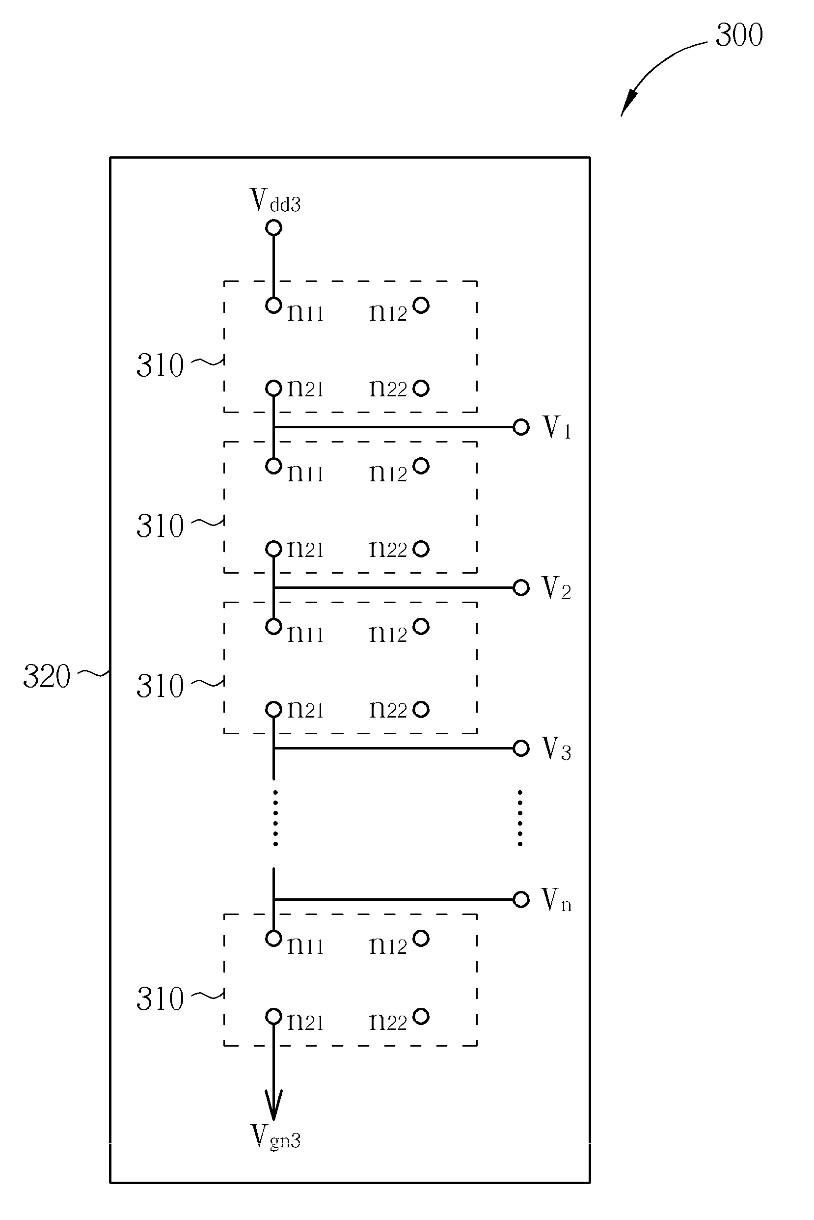
[0008]It is therefore one of the objectives of the present invention to provide a resistive module, a voltage divider employing the resistive module and a circuit layout method thereof, to provide more precise resistive values required for improving an actual Gamma curve of a display apparatus, without significantly increasing the cost and layout area, in order to solve the aforementioned problems.

Problems solved by technology

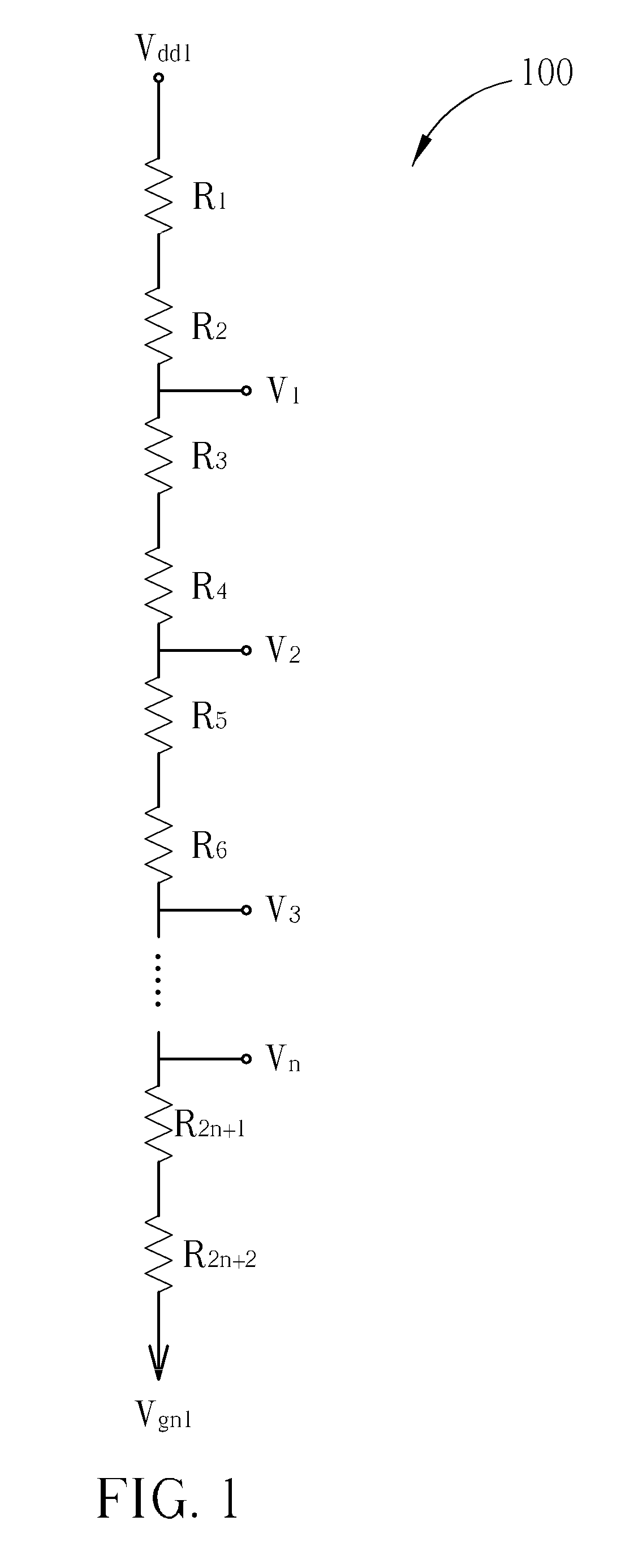
However, since the divided voltage generating manner employed in the conventional Gamma voltage divider 100 only has one fixed resistance arrangement (e.g., R1+R2, R3+R4, R2n+1+R2n+2); this leads to the derived resistive value (e.g., R1+R2) failing to match the ideal resistive value required by the ideal Gamma curve and consequently degrades the display quality of the LCD.
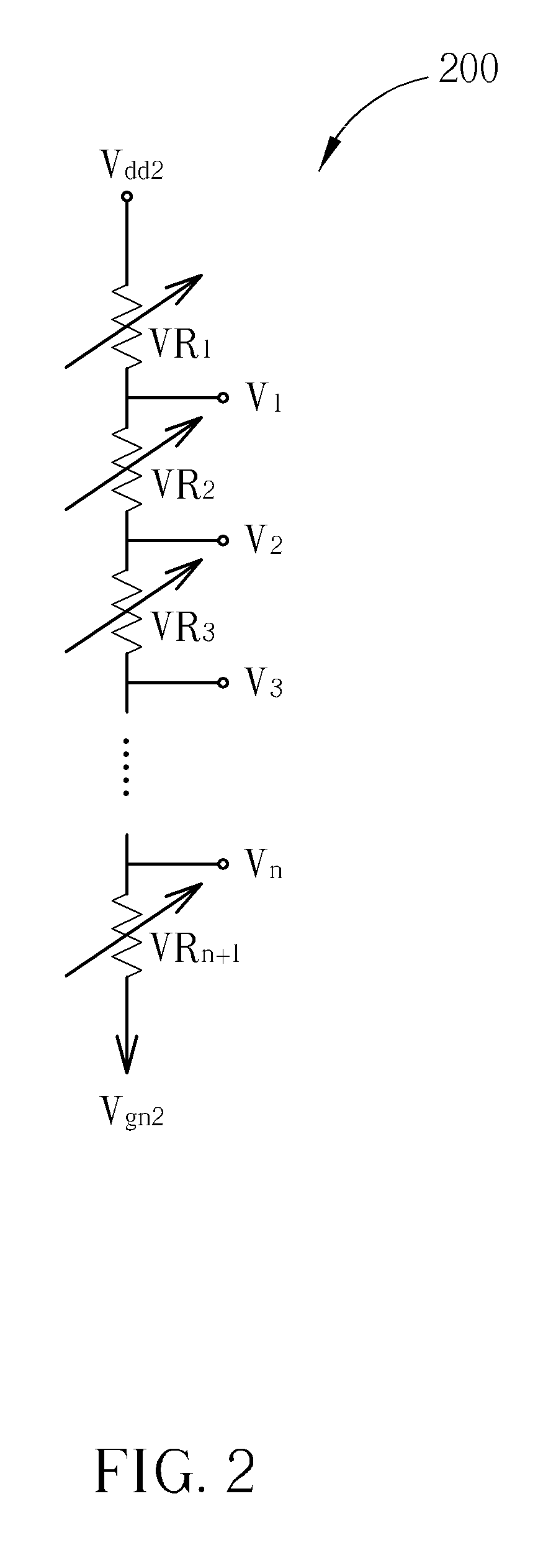
The conventional Gamma voltage divider 200, however, also has some drawbacks such as higher cost due to implementation of variable resistors and increased layout area due to larger sizes of the variable resistors.

Method used


Image

  • Resistive module, voltage divider and related layout methods
  • Resistive module, voltage divider and related layout methods
  • Resistive module, voltage divider and related layout methods

Examples


Embodiment Construction

[0026]Certain terms are used throughout the following description and claims to refer to particular system components. As one skilled in the art will appreciate, manufacturers may refer to a component by different names. This document does not intend to distinguish between components that differ in name but not function. In the following discussion and in the claims, the terms “including” and “comprising” are used in an open-ended fashion, and thus should be interpreted to mean “including, but not limited to . . . ” The terms “couple” and “couples” are intended to mean either an indirect or a direct electrical connection. Thus, if a first device couples to a second device, that connection may be through a direct electrical connection, or through an indirect electrical connection via other devices and connections.

[0027]Please refer to FIG. 3; FIG. 3 is a diagram illustrating a Gamma voltage divider 300 according to an embodiment of the present invention. In this embodiment, Gamma vol...


PUM


Abstract

The present invention includes a resistive module, the resistive module including a plurality of nodes and at least a resistive component. The plurality of nodes include an input terminal and an output terminal of the resistive module; the resistive component is electronically connected between the input terminal and the output terminal of the resistive module to thereby make the input terminal and the output terminal have a specified resistive value therebetween. In addition, the resistive component is electrically connected between two nodes of a node pair among the nodes, and each resistive component has a corresponding predetermined resistive value.

Description

BACKGROUND OF THE INVENTION[0001]1. Field of the Invention[0002]The present invention relates to layout methods and devices thereof, and more particularly, to a resistive module, a voltage divider using the resistive module, and layout methods thereof.[0003]2. Description of the Prior Art[0004]Extensive experiments and data records have shown that a relationship between brain perception of human beings and luminance can be expressed by an equation: Y=AXΓ; where a curve defined by such an equation is named a Gamma curve, and the magnitude of Γ (i.e., Gamma) differs from around 2.0 to 2.5 for various conditions. At present, display technologies need to execute calibrating operations for ensuring that data displayed by a display apparatus is in proportion to the brain perception precisely. Therefore, to achieve the goal of making the actual Gamma curve measured by a display apparatus more approximate to an ideal Gamma curve, it is required to devise a plurality of voltages (e.g., Gamma...

Claims


Application Information

Patent Timeline
Patent Type & Authority Applications(United States)
IPC IPC(8): G09G3/36H01C7/22G05F1/656
CPCG09G3/3688G09G2310/027H01C13/02H01C1/16H01C1/14
Inventor WEI, I-CHINGLIU, KUAN-HUNGCHU, YI-NAN
Owner CHUNGHWA PICTURE TUBES LTD
Learn More