Visual tracking system and method thereof

a tracking system and visual technology, applied in the field of visual tracking system, can solve the problems of loss of detecting object, inability to obtain actual position of foreground, and easy affecting the final result, and achieve the effect of maximizing the obtained information

Active Publication Date: 2009-10-22
NAT TAIWAN UNIV
View PDF2 Cites 52 Cited by
  • Summary
  • Abstract
  • Description
  • Claims
  • Application Information

AI Technical Summary

Benefits of technology

[0016]Therefore, the present invention provides a visual tracking system and its method for recording a

Problems solved by technology

However, one of disadvantages of this method is that the final result can be easily affected by the noises of the camera or the illumination changes of the environment.
As a result, the subtraction result will contain both the foreground and the background, thus, the actual position of the foreground cannot be obtained.
Further, when the object stops moving, the motion detection of the system cannot continue to locate the object resulting the loss of its detecting object.
Moreover, since the camera must be fixed to a definite position, the viewing angle would be rigidly constrained and limited.
In applications of the conventional surveillance system, the real-time characteristic of the system is an important issue, and a standard camera can normally capture 30 frames per second.
In other words, the time re

Method used


Image

  • Visual tracking system and method thereof
  • Visual tracking system and method thereof
  • Visual tracking system and method thereof

Examples


Embodiment Construction

[0023]The above and other objects, features and advantages of the present invention will become apparent from the following detailed description taken with the accompanying drawing.

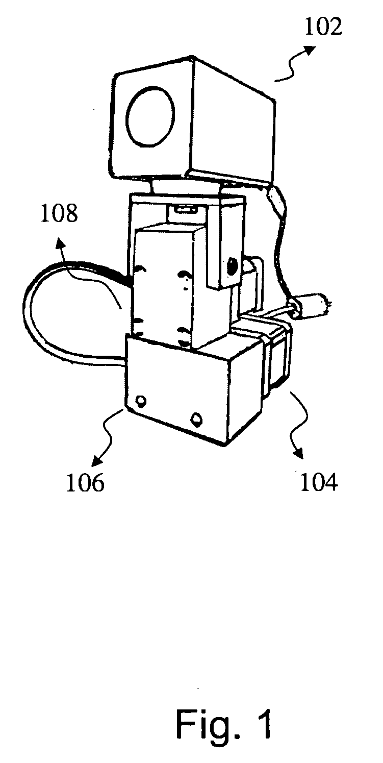
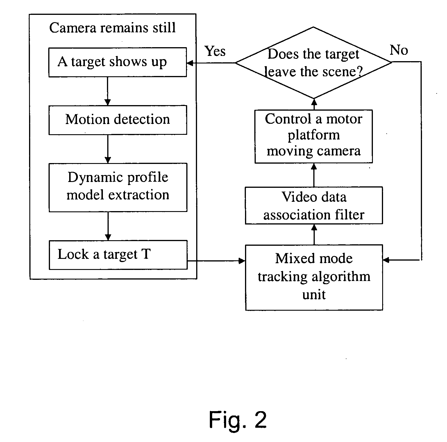
[0024]Referring to FIG. 1 for a schematic view of a visual tracking system in accordance with a preferred example of the invention, the visual tracking system comprises an image sensor unit 102, an active moving platform 104, a horizontal motor 106, an inclined motor 108, an image processor unit 110 (not shown in the figure), a hybrid tracking algorithm unit 112 (not shown in the figure), and a visual probability data association filter 114 (not shown in the figure). The image sensor unit 102 continuously captures images of a monitored scene. The flow chart of operating a tracking system is shown in FIG. 2 and described as follows.

[0025]Referring to FIG. 2 for a flow chart of operating a tracking system and its method in accordance with the preferred example of the invention, a target shows up, and the im...


PUM


Abstract

The present invention provides a visual tracking system and its method comprising: a sensor unit, for capturing monitored scenes continuously; an image processor unit, for detecting when a target enters into a monitored scene, and extracting its characteristics to establish at least one model, and calculating the matching scores of the models; a hybrid tracking algorithm unit, for combining the matching scores to produce optimal matching results; a visual probability data association filter, for receiving the optimal matching results to eliminate the interference and output a tracking signal; an active moving platform, for driving the platform according to the tracking signal to situate the target at the center of the image. Therefore, the visual tracking system of the present invention can help a security camera system to record the target in details and maximize the visual information of the intruding target.

Description

FIELD OF THE INVENTION[0001]The present invention relates to a visual tracking system and its method, and more particularly to a system and a method of timely tracking an object by a combination of image characteristics.BACKGROUND OF THE INVENTION[0002]At present, the conventional video surveillance systems in the market comprise mainly the simple function of motion detection which can detect images by utilizing the principle of image subtraction. In other words, the method of the subtraction principle is based on a presumption that a camera and an image background are both in a motionless position, and the image intensities of corresponding pixels of two adjacent photos at a specific time is subtracted. If the result is greater than a user-defined threshold, then it would be considered as an indication of a moving object. However, one of disadvantages of this method is that the final result can be easily affected by the noises of the camera or the illumination changes of the enviro...

Claims


Application Information

Patent Timeline
IPC IPC(8): G06K9/00
CPCG06T7/20H04N5/232G06T2207/10016H04N23/61H04N23/695
Inventor HUANG, CHENG-MINGLIN, YI-TZNFU, LI-CHENHSIAO, PEI-YUNG
Owner NAT TAIWAN UNIV
Why Eureka
Try Eureka