Optical fiber

a technology of optical fiber and fiber, applied in the field of optical fiber, can solve the problems of increased cost of optical fiber, low bending loss, and large amount of fluorine for low transmission loss

Active Publication Date: 2009-10-22
FURUKAWA ELECTRIC CO LTD
View PDF3 Cites 22 Cited by
  • Summary
  • Abstract
  • Description
  • Claims
  • Application Information

AI Technical Summary

Problems solved by technology

Furthermore, particularly for an optical fiber used in an optical fiber cable installed as a land transmission line, a low bending loss is required because a bending and a lateral pressure are applied on the optical fiber at the time of setting it in a slot of a cable.
However, the convention optical fiber that realizes a low transmission loss requires a massive amount of fluorine at the time of manufacturing the fiber because the whole cladding layer is doped with fluorine.
As a result, there has been a problem that the cost of the optical fiber is increased.

Method used


Image

  • Optical fiber
  • Optical fiber
  • Optical fiber

Examples


Embodiment Construction

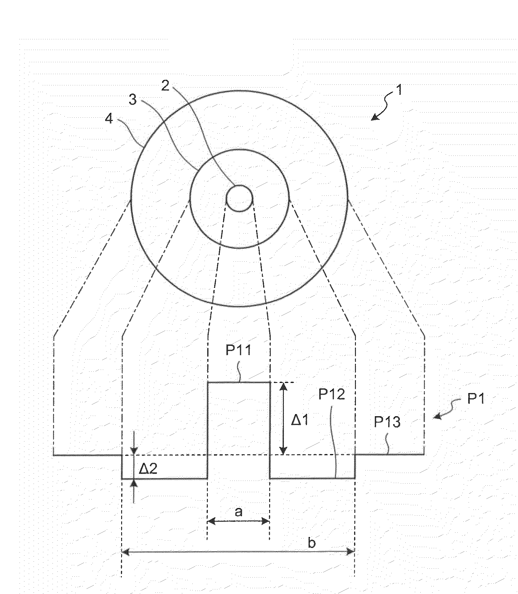
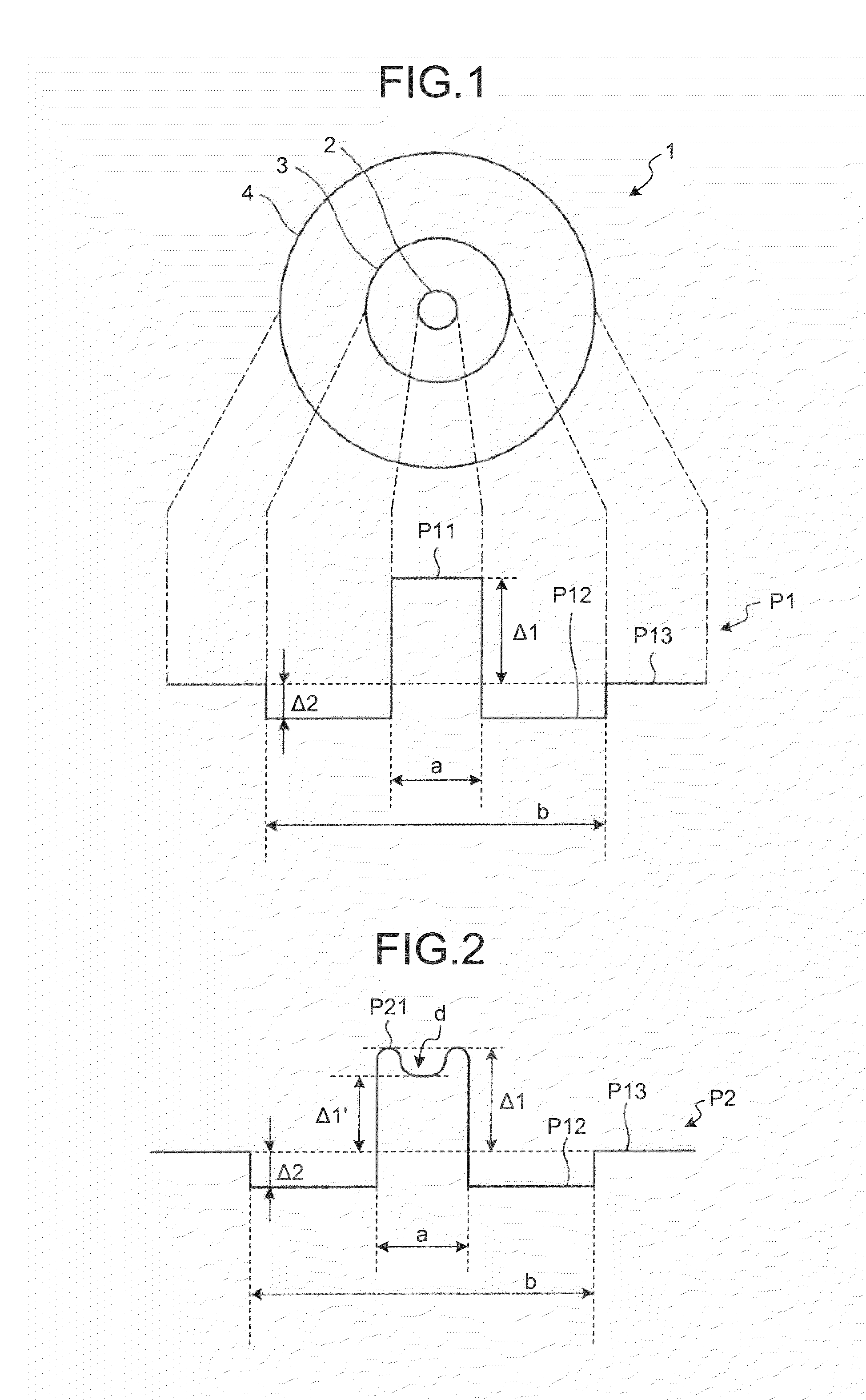
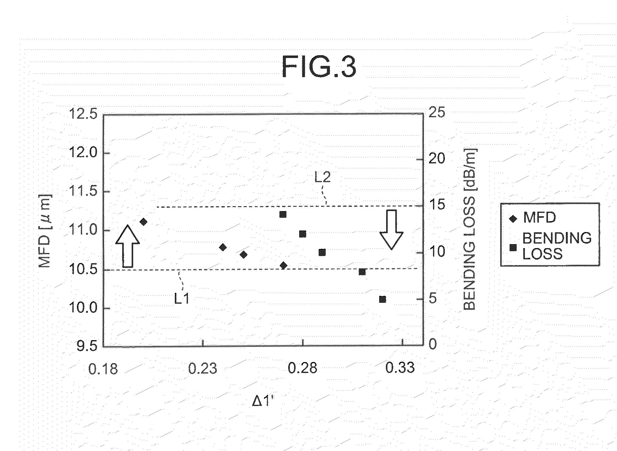
[0021]Exemplary embodiments of an optical fiber according to the present invention will be explained in detail below with reference to the accompanying drawings. However, the present invention is not to be considered limited to the embodiments. A bending loss mentioned in the specification means a bending loss under a condition that the optical fiber is wound with a diameter of 20 millimeters. Other terminologies not specifically defined in this specification comply with the definitions and the measurement methods in the ITU-T G. 650.1.

[0022]FIG. 1 is a schematic diagram for illustrating a cross section of an optical fiber 1 according to an embodiment of the present invention and its corresponding refractive index profile. As shown in FIG. 1, the optical fiber 1, which is made of silica-based glass, includes a center core region 2 that contains germanium, an outer core layer 3 that contains fluorine, and a cladding layer 4 made of pure silica glass. The outer core layer 3 is formed ...


PUM


Abstract

A relative refractive index difference Δ1 between a center core region and a cladding layer is 0.30% to 0.35%, a relative refractive index difference Δ2 between an outer core layer and the cladding layer is −0.10% to −0.04%, and Δ1:Δ2 is 2.5:1 to 7.5:1. A diameter of the center core region is 9.0 μm to 10.5 μm, and a ratio of diameters of the center core region and the outer core layer is 0.20 to 0.35. A cutoff wavelength is 1310 nm or shorter, a zero dispersion wavelength is 1285 nm to 1345 nm, and at a wavelength of 1550 nm, an MFD is 10.5 μm or larger, a transmission loss is 0.185 dB / km or lower, and a bending loss is 15 dB / m or lower.

Description

CROSS-REFERENCE TO RELATED APPLICATIONS[0001]This application is a continuation of PCT / JP2008 / 064416 filed on Aug. 11, 2008, the entire content of which are incorporated herein by reference.BACKGROUND OF THE INVENTION[0002]1. Field of the Invention[0003]The present invention relates to an optical fiber used as an optical transmission line for an optical communication.[0004]2. Description of the Related Art[0005]As a conventional optical transmission line for an optical communication, a standard single-mode optical fiber (SMF) defined in the ITU-T (International Telecommunication Union Telecommunication Standardization Sector) G. 652 is most commonly used.[0006]For an optical fiber used as an optical transmission line for a long-haul optical communication, a transmission loss far lower than that of the standard SMF is required to extend a transmission distance and to reduce a load to an optical amplifier as an optical repeater. In addition, a nonlinearity even lower than that of the ...

Claims


Application Information

Patent Timeline
Patent Type & Authority Applications(United States)
IPC IPC(8): G02B6/036
CPCG02B6/02019G02B6/03627G02B6/03611
Inventor KUMANO, NAOMI
Owner FURUKAWA ELECTRIC CO LTD
Why Eureka
Try Eureka