Ventilation system

a technology of ventilation system and air flow rate, which is applied in ventilation system, lighting and heating apparatus, heating types, etc., to achieve the effect of improving air flow rate, increasing flexibility in dimensioning the unit, and improving air flow

Inactive Publication Date: 2009-10-22
NUCLIMATE AIR QUALITY SYST
View PDF18 Cites 30 Cited by
  • Summary
  • Abstract
  • Description
  • Claims
  • Application Information

AI Technical Summary

Benefits of technology

[0016](6) increased flexibility in dimensioning the unit to fit in a required space and still provide a required airflow (for example, trading off the vertical dimension against foot print size);
[0017](7) greater area available to receive return air from the room;
[0018](8) greater volume available for thermal treatment devices for the return air within the volume of the mixing chamber;
[0019](9) improved air flow rate, improved air flow per unit of foot print area and improved air flow per unit of device volume;
[0020](10) decreased installation costs; and / or
[0021](11) decreased materials costs.

Problems solved by technology

For example, some or all of the discussed publications may not be sufficiently early in time, may not reflect subject matter developed early enough in time and / or may not be sufficiently enabling so as to amount to prior art for patent law purposes.

Method used


Image

  • Ventilation system
  • Ventilation system
  • Ventilation system

Examples


Embodiment Construction

[0051]Discussion will begin with a couple of simplified, not necessarily preferred embodiments of the present invention (shown in FIGS. 23-26) to illustrate some of the inventive concepts. Discussion will then proceed to a couple of preferred embodiments (shown in FIGS. 2 to 22).

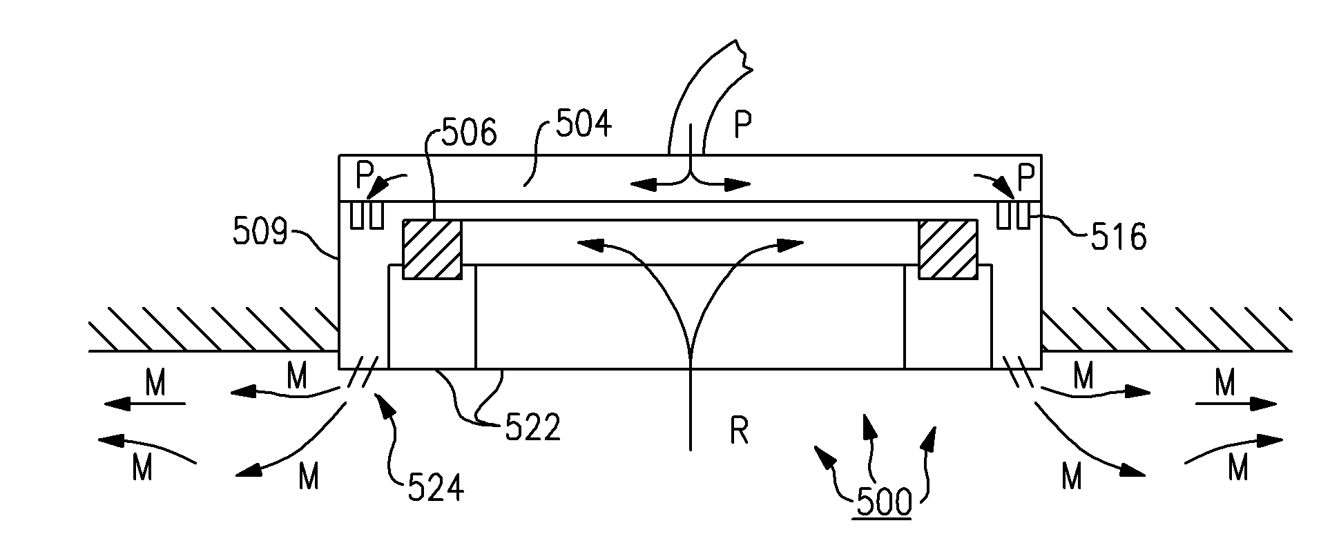
[0052]FIGS. 23a and 23b show ventilation system 400 according to the present invention, including: unitary plenum portion 404; heating / cooling unit 406; drainage base 407; mixing chamber outer wall 409; and venturi nozzles 416. Primary air P is blown into the unitary plenum portion from a primary air source (see DEFINITIONS section). The primary air is then forced through the nozzles 416 and down into the mixing chamber 406. Although only two nozzles are shown in FIGS. 23a and 23b, it is highly preferred that more nozzles be provided so that one or more rows of nozzles extend at least substantially all the way around the perimeter of system 400. In this embodiment, the mixing chamber is defined by the mixing...


PUM


Abstract

The present invention is directed to a 360 degree ventilation system with a single unitary plenum. The present invention is also directed to a 360 degree ventilation system with a single mixing chamber extending at least substantially entirely around the perimeter of the blow ventilation system. The present invention is also directed to a 360 degree ventilation system with a heating/cooling units that extend substantially all the way around the perimeter of the ventilation system. The present invention is also directed to a 360 degree ventilation system with a single return air chamber.

Description

RELATED APPLICATION[0001]The present application claims priority to U.S. provisional patent application No. 61 / 045,462, filed on Apr. 16, 2008; all of the foregoing patent-related document(s) are hereby incorporated by reference herein in their respective entirety(ies).FIELD OF THE INVENTION[0002]The The present invention relates to ventilation systems and more particularly a four way blow ventilation systems located between a drop ceiling and a structural ceiling of a building.DESCRIPTION OF THE RELATED ART[0003]FIGS. 1a and 1b show a conventional four way blow ventilation system 100 for installation and use between a drop ceiling and a structural ceiling of a building. System 100 includes four separate induction units 102a, 102b, 102c, 10d. Each induction unit includes: a plenum 104; a heating / cooling unit 106; a drainage base 107; a mixing chamber outer wall 109; and nozzles 116. The induction unit mixes return air (shown by arrow R) from the building with primary air (shown by a...

Claims


Application Information

Patent Timeline
Patent Type & Authority Applications(United States)
IPC IPC(8): F24F7/04F24F1/0323
CPCF24F1/0059F24F2221/14F24F2013/0616F24F1/01F24F1/0323
Inventor MILLER, JAMES H.SHULTES, WILLIAM R.
Owner NUCLIMATE AIR QUALITY SYST
Why Eureka
Try Eureka