Supercharge Your Innovation With Domain-Expert AI Agents!

Golf Tee

a golf tee and tee technology, applied in the field of golf tees, can solve the problems of difficult driving into heavy ground, high tee mass, and high cost of tees, and achieve the effect of minimizing contact, excellent strength and ground penetration

Active Publication Date: 2009-10-22
WHITEHOUSE ROBERT S
View PDF25 Cites 13 Cited by
  • Summary
  • Abstract
  • Description
  • Claims
  • Application Information

AI Technical Summary

Benefits of technology

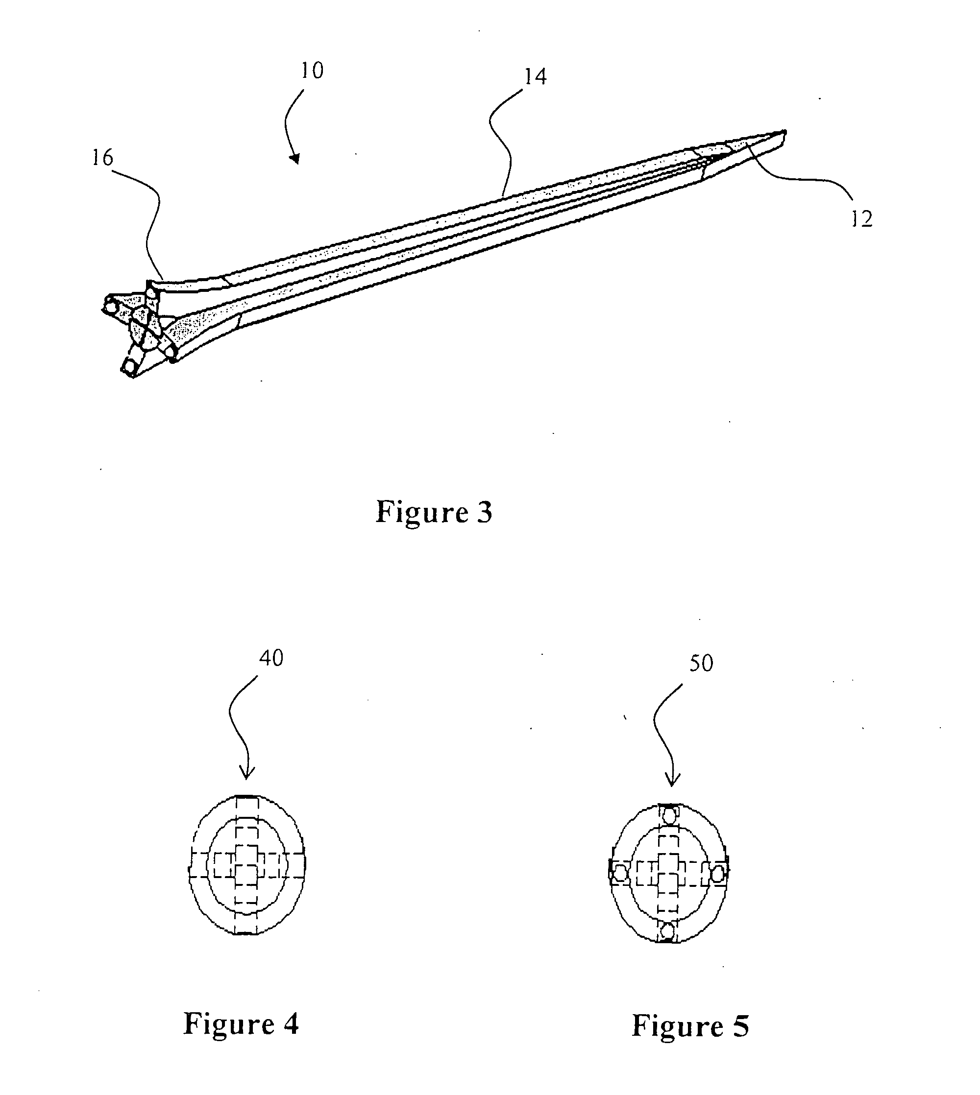
[0011]The present invention relates to a novel golf tee having a shaft that is cross-shaped in cross-section and provides excellent strength and ground penetration. The golf tee comprises a head design that can minimize contact between a golf ball and the tee. The golf tee can be manufactured, for example, from non-degradable or biodegradable polymeric compositions. The golf tee can be mass produced using, for example, conventional compression molding or injection molding operations.

Problems solved by technology

The design shown has a very substantial shaft cross-section making it potentially difficult to drive into heavy ground.
The mass of the golf tee is also likely to be substantial, potentially making the tee relatively expensive.
Whilst the performance of the driving action may be improved by adjusting the position of the seat portion, the design is highly complex making it uneconomic for normal golf activities.
The form of this golf tee would be extremely difficult to mass-produce, thus making it less commercially viable.
This design would be expensive and extremely difficult to replicate for a large volume market such as commercial golf tees.
None of the above patent applications describe a golf tee which meets all the current requirements of low cost production, low mass, good penetration into the ground under all conditions and the ability to balance a golf ball on the head component with minimal contact area.

Method used


Image

  • Golf Tee
  • Golf Tee
  • Golf Tee

Examples


example 1

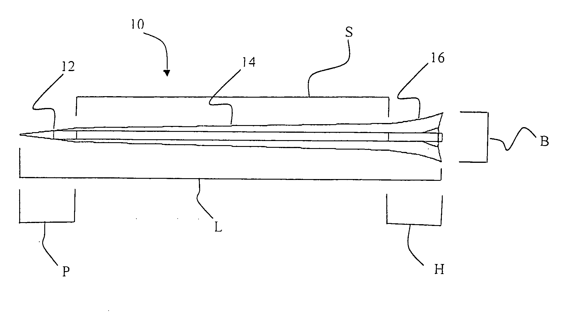
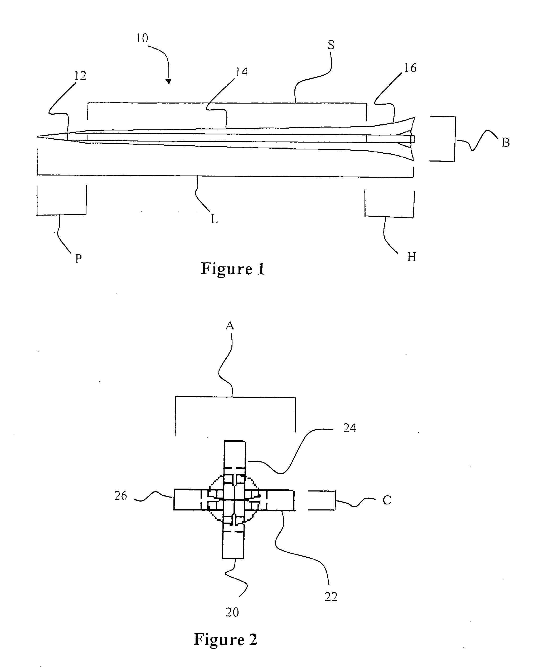
[0039]A golf tee of geometry shown in FIG. 1, having a total length of 75 millimeters (mm) and a head of maximum dimensions 8.9 mm, was injection molded from the biodegradable polymeric system Starpol 2189, manufactured by Stanelco Co. The composition is claimed to be a blend of thermoplastic starch, polylactic acid, and mineral filler. The mass of the molded tee was approximately 0.88 gram.

example 2

[0040]A golf tee of geometry shown in FIG. 1, having a total length of 50 mm and a head of maximum dimensions 8.9 mm, was injection molded in the biodegradable polymeric system Starpol 2189, manufactured by Stanelco Co. The mass of the molded tee was approximately 0.72 gram.

Example 3

[0041]A golf tee of geometry shown in FIG. 1, having a total length of 75 mm and a head of maximum dimensions 8.9 mm, was produced using a photolithographic technique with an epoxide acrylate resin. The mass of the molded tee was approximately 0.83 gram.

example 4

[0042]A golf tee of geometry shown in FIG. 1, having a total length of 75 mm, and a head of maximum dimensions 9.2 mm, and a shaft arm width of 2.1 mm, was injection molded in a biodegradable polymeric system Starpol 2189, manufactured by Stanelco Co. The composition is claimed to be a blend of thermoplastic starch, polyvinyl alcohol and mineral filler; the mass of the molded tee was approximately 1.1 grams.

Assessment of Ground Penetration

[0043]The golf tee was manually pushed into light loam and heavy dry clay soil compositions found on a typical golf course. The ease of penetration of the tee into the ground was assessed together with the shape of the hole made by the golf tee. A standard wood golf tee and a new Evolve Golfs EPOCH™ golf tee marketed by Evolve Golf, Inc., were used for comparison.

Golf teeLight loamHeavy dry clayWoodEasy to push in, someEasy to push in, distortiondistortion of the hole, slightof the hole, slight instabilityinstability in holding golfin holding golf ...


PUM


Abstract

According to various embodiments, the present teachings comprise a golf tee. The golf tee can comprise a point section, a shaft section, and a head section. The shaft section can comprise four opposing arms configured to allow for improved ground penetration. The head section can comprise a circular dish having a rim with a number of raised points disposed on the rim. The head section can comprise opposing arms, each having a raised point.

Description

FIELD OF THE INVENTION[0001]This invention relates to golf tees.BACKGROUND TO THE INVENTION[0002]Many designs for golf tees exist. Those that are acceptable for use in competition golf matches comprise a shaft section with a point for inserting the tee into the ground and a head or cup component for holding the golf ball. The nature of the shaft design is critical in providing a tee that is easily inserted into the ground with minimal force, but good holding power in all soil conditions. The head geometry has to provide a location point for the golf ball and allow for easy removal during the driving shot with no adverse effect on the direction and trajectory of the golf ball.[0003]U.S. Pat. No. 502,972, published Mar. 15, 2005, describes a conventional tapered circular shaft design with a head having four raised portions that provide contact points for supporting the golf tee. The design shown has a very substantial shaft cross-section making it potentially difficult to drive into h...

Claims


Application Information

Patent Timeline
Patent Type & Authority Applications(United States)
IPC IPC(8): A63B57/00
CPCA63B57/0018A63B57/10A63B57/00
Inventor WHITEHOUSE, ROBERT S.
Owner WHITEHOUSE ROBERT S
Features
  • R&D
  • Intellectual Property
  • Life Sciences
  • Materials
  • Tech Scout
  • Unparalleled Data Quality
  • Higher Quality Content
  • 60% Fewer Hallucinations
Learn More