In-vehicle sensor-based calibration algorithm for yaw rate sensor calibration

a technology of yaw rate and calibration algorithm, which is applied in the direction of instruments, structural/machine measurement, navigation instruments, etc., can solve the problems of unsuitable navigation and heading determination functions without proper error correction techniques, and gps receivers suffer from sky visibility-related limitations,

Active Publication Date: 2009-10-22
GM GLOBAL TECH OPERATIONS LLC
View PDF35 Cites 52 Cited by
  • Summary
  • Abstract
  • Description
  • Claims
  • Application Information

AI Technical Summary

Benefits of technology

[0010]In accordance with the teachings of the present invention, a system and method are disclosed for calibrating a vehicle heading sensor, such as a yaw-rate sensor, when GPS signals are not available using a bias update model that employs a bias gain factor. In order for the bias update model to be accurate, the vehicle should be traveling relatively straight. One e

Problems solved by technology

However, GPS receivers suffer from sky visibility-related limitations, for example, in urban canyons and areas with dense tree cover.
Further, GPS signals may suffer from multi-path errors or cross-correlation errors in such areas.
Automotive-grade inertial sensors, such as yaw-rate sensors and accelerometers, have highly variable bias and scale characteristics that cause sensor drift that typically makes them un-suitable for nav

Method used


Image

  • In-vehicle sensor-based calibration algorithm for yaw rate sensor calibration
  • In-vehicle sensor-based calibration algorithm for yaw rate sensor calibration

Examples


Embodiment Construction

[0014]The following discussion of the embodiments of the invention directed to a system and method for calibrating a yaw-rate sensor when GPS signals are not available using a bias update model is merely exemplary in nature, and is in no way intended to limit the invention or its applications or uses.

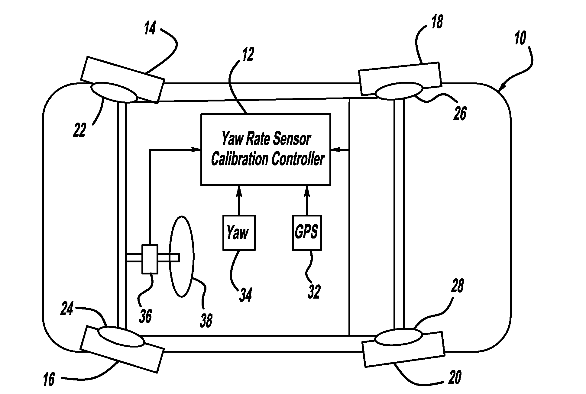
[0015]FIG. 1 is a plan view of a vehicle 10 including a yaw-rate sensor calibration controller 12, according to an embodiment of the present invention. The vehicle 10 also includes front wheels 14 and 16 and rear wheels 18 and 20. The wheels 14, 16, 18 and 20 each include a wheel speed sensor 22, 24, 26 and 28, respectively, that provide wheel speed and / or wheel rotation signals to the controller 12. A GPS receiver 32 provides GPS signals to the controller 12, and a yaw-rate sensor 34 provides vehicle yaw rate sensor signals to the controller 12. Also, a hand-wheel angle sensor 36 provides a steering wheel angle signal of the rotation of a steering wheel 38 to the controller 12.

[0016]Th...


PUM


Abstract

A system and method for calibrating a vehicle heading sensor, such as a yaw-rate sensor, when GPS signals are not available using a bias update model that employs a bias gain factor. In order for the bias update model to be accurate, the vehicle should be traveling relatively straight. One embodiment of the present invention uses three thresholds to determine if the vehicle is traveling straight. These thresholds include a yaw-rate threshold, a steering wheel angle threshold and a wheel speed threshold. If all three of the thresholds indicate that the vehicle is traveling straight, then the update bias model can be used to calibrate the yaw-rate sensor.

Description

BACKGROUND OF THE INVENTION[0001]1. Field of the Invention[0002]This invention relates generally to a system and method for calibrating a heading sensor, such as a yaw-rate sensor, and, more particularly, to a system and method for removing sensor bias errors from a yaw-rate sensor to use the yaw-rate sensor to provide an accurate vehicle heading when GPS signals are not available, where the system and method employ a bias update model to calibrate the sensor using the yaw-rate, a steering wheel angle and a differential wheel speed to identify time windows where the vehicle is traveling relatively straight.[0003]2. Discussion of the Related Art[0004]GPS signals, or other Global Navigation Satellite System (GNSS) signals, can provide accurate positioning and navigation. However, GPS receivers suffer from sky visibility-related limitations, for example, in urban canyons and areas with dense tree cover. Further, GPS signals may suffer from multi-path errors or cross-correlation errors ...

Claims


Application Information

Patent Timeline
IPC IPC(8): G01M17/00
CPCB60W40/11B60W40/112G01C25/00G01C21/28B60W40/114
Inventor BASNAYAKE, CHAMINDA
Owner GM GLOBAL TECH OPERATIONS LLC
Why Eureka
Try Eureka