
System Power Capping Using Information Received From The Installed Power Supply

Active Publication Date: 2009-10-22
LENOVO GLOBAL TECH INT LTD
View PDF14 Cites 22 Cited by
  • Summary
  • Abstract
  • Description
  • Claims
  • Application Information

AI Technical Summary

Benefits of technology

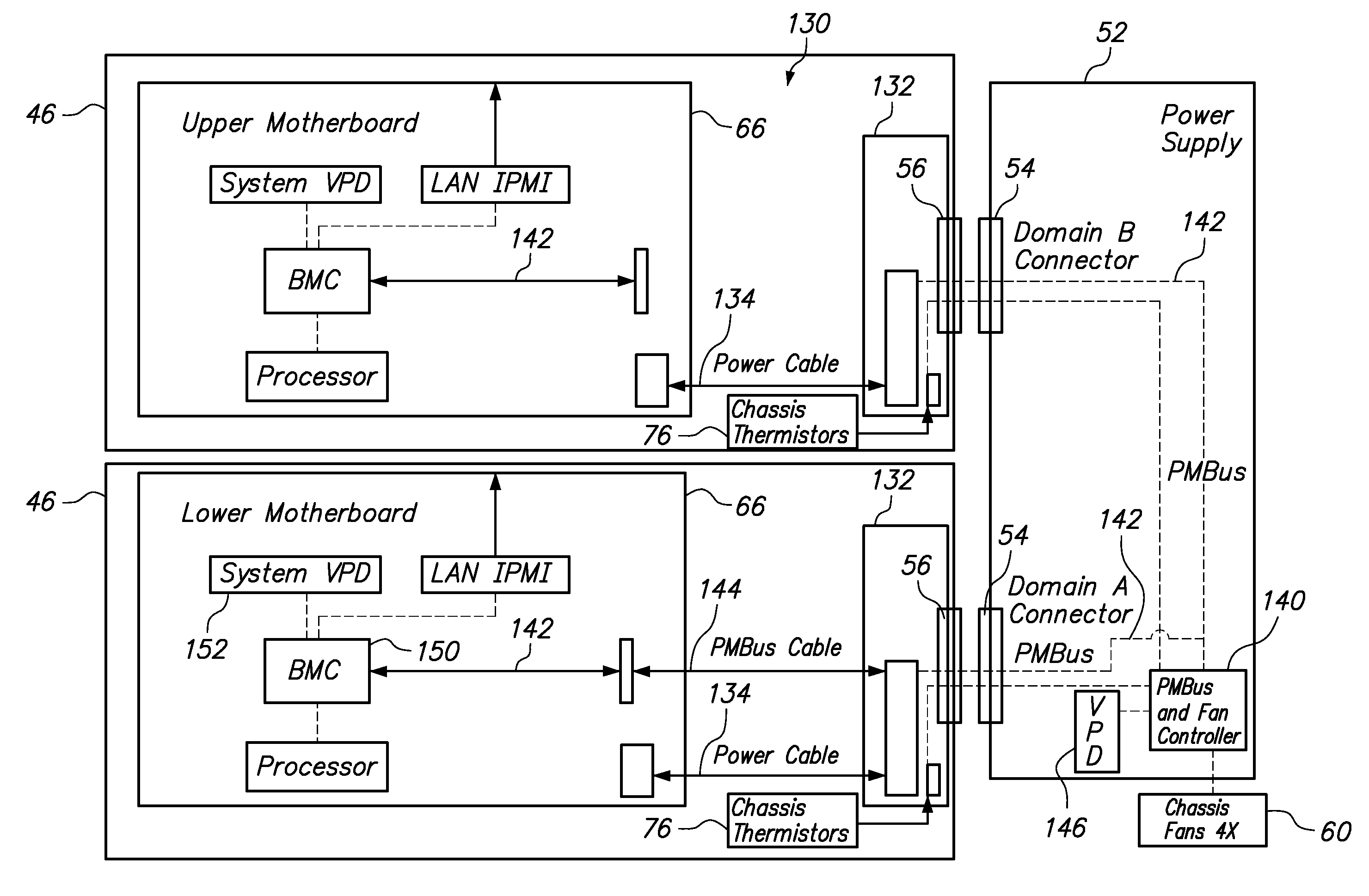
[0007]Another embodiment of the invention provides a method of controlling power consumption in a computer system. The method comprises selectively coupling a power circuit and a power management bus between a motherboard having a baseboard management controller and a power supply having a power management bus controller, sending a power capacity rating of the power supply from the power management bus controller to the baseboard management controller over the power management bus, and controlling the operation of the motherboard to prevent power consumption from exceeding a power cap that is equal to the power capacity rating of the power supply. Preferably, the power supply is interchangeably selected from a group of power supplies having different power capacities, each power supply having an associated power management bus controller with memory storing the power capacity rating of the associated power supply. Most preferably, the step of sending the power capacity of the power supply to the baseboard management controller is performed in response to booting the motherboard.

Problems solved by technology

Unfortunately, providing excess and unused power capacity increases infrastructure and operating costs.
Furthermore, if the data center can support only a limited total power, excess power means that fewer electronic components can be installed in the data center.
However, because software is subject to modification or failure, regulations generally prohibit reliance on software to control the total power to the system.

Method used


Image

  • System Power Capping Using Information Received From The Installed Power Supply
  • System Power Capping Using Information Received From The Installed Power Supply
  • System Power Capping Using Information Received From The Installed Power Supply

Examples


Embodiment Construction

[0016]One embodiment of the present invention provides a computer system, comprising a motherboard and a power supply interchangeably selected from a group of power supplies having different power capacities, each power supply having an associated power management bus controller with memory storing the power capacity of the associated power supply. A power circuit provides power from the power supply to the motherboard, wherein the motherboard has a processor and a baseboard management controller. The system further comprises a power management bus providing communication between the baseboard management controller and the power management bus controller associated with the selected power supply, wherein the power management bus controller provides the stored power capacity to the baseboard management controller, and wherein the baseboard management controller limits operation of the processor to control the amount of power consumed from exceeding the power capacity of the selected ...


PUM


Abstract

A computer system comprising a motherboard and a power supply having an associated power management bus controller with memory storing the power capacity of the associated power supply. A power circuit provides power from the power supply to the motherboard, wherein the motherboard has a processor and a baseboard management controller. The system further comprises a power management bus providing communication between the baseboard management controller and the power management bus controller associated with the selected power supply, wherein the power management bus controller provides the stored power capacity to the baseboard management controller. This allows the baseboard management controller to limit operation of the processor to control the amount of power consumed from exceeding the power capacity of the selected power supply. The power capacity of the power supply may be sent to the baseboard management controller in response to booting the motherboard.

Description

BACKGROUND OF THE INVENTION[0001]1. Field of the Invention[0002]The present invention relates to methods and systems for supplying power to a computer system, and more specifically to the methods and systems for controlling the amount of power consumed by computer systems.[0003]2. Background of the Related Art[0004]Modern data centers include large numbers of electronic components that require electrical power to operate. In fact, sufficient power capacity must be provided to support each of the electronic components over an operating range up to the maximum possible power that the components can draw. The maximum possible power drawn by an electronic component, or group of components, is sometimes referred to as the maximum label power. In a rack for supporting and operating computer systems, such as a group of servers and supporting hardware, the power circuits must be able to supply enough power to operate the rack at the most extreme configuration of components and the maximum w...

Claims


Application Information

Patent Timeline
IPC IPC(8): G06F1/26
CPCG06F1/3203G06F1/26
Inventor CLEMO, RAYMOND MATHEWGRUENDLER, NICKOLAS JOHNLOEBACH, BETH FRAYNEMCKNIGHT, GREGORY JOSEPH
Owner LENOVO GLOBAL TECH INT LTD
Learn More