Punch device with adjustment subassembly as retrofit insert or as original equipment

a technology of sub-assembly and punch, which is applied in the direction of metal-working equipment, metal-working equipment, manufacturing tools, etc., can solve the problems of long downtime of equipment, time-consuming disassembly, laborious operation, etc., and achieve the effect of preventing misalignment or uneven wear

Active Publication Date: 2009-10-29
MATE PRECISION TOOLING
View PDF2 Cites 26 Cited by
  • Summary
  • Abstract
  • Description
  • Claims
  • Application Information

AI Technical Summary

Benefits of technology

[0005]Another object is to provide a manually adjustable punch that is constructed so as to reliably pr

Problems solved by technology

Many punch assemblies in commercial use such as the punch assembly described in U.S. Pat. No. 4,989,484 while otherwise very good require time-consuming disassembly using hand tools in order to remove the punch to sharpen the punch tip followed by reinstallation and readjustment of the length of the punch.
This operation is labor intensive and, of course, lengthens the downtime of the equipment.
Reduced press productivity is problematic particularly with respect to punch assemblies used in high-speed automated punch presses and pu

Method used


Image

  • Punch device with adjustment subassembly as retrofit insert or as original equipment
  • Punch device with adjustment subassembly as retrofit insert or as original equipment
  • Punch device with adjustment subassembly as retrofit insert or as original equipment

Examples


Embodiment Construction

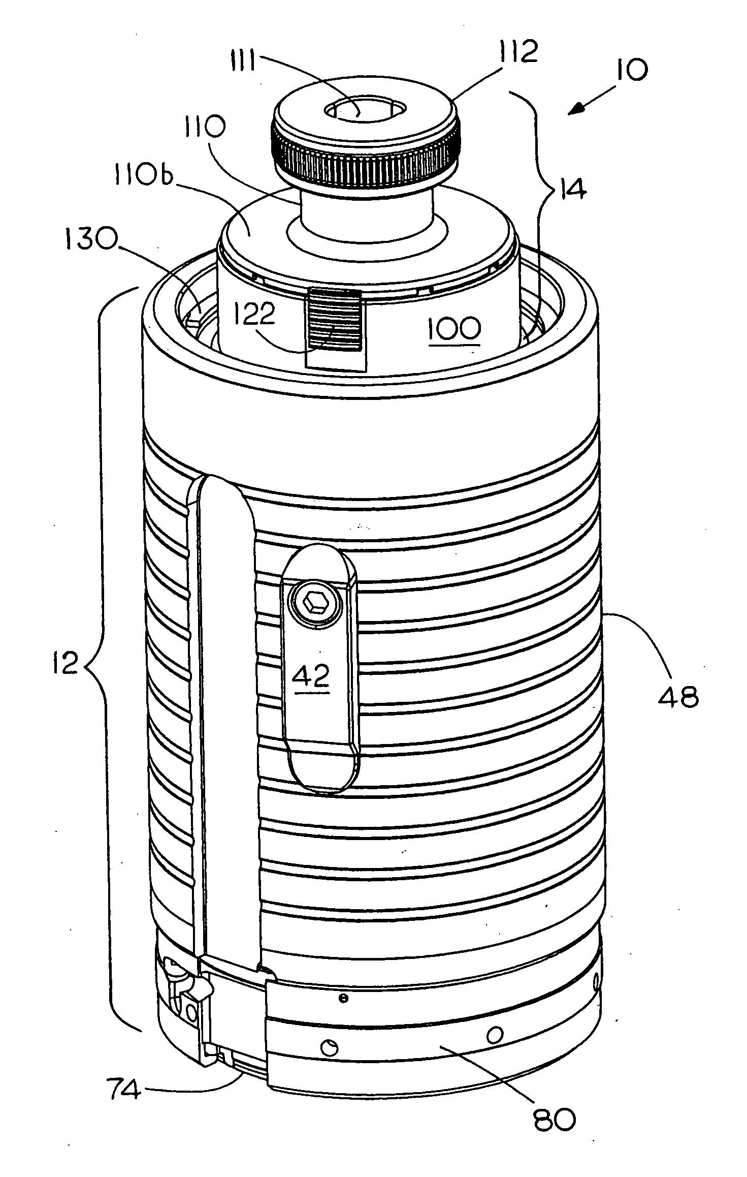
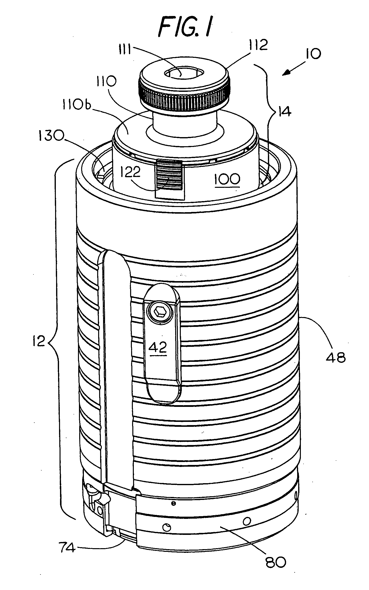
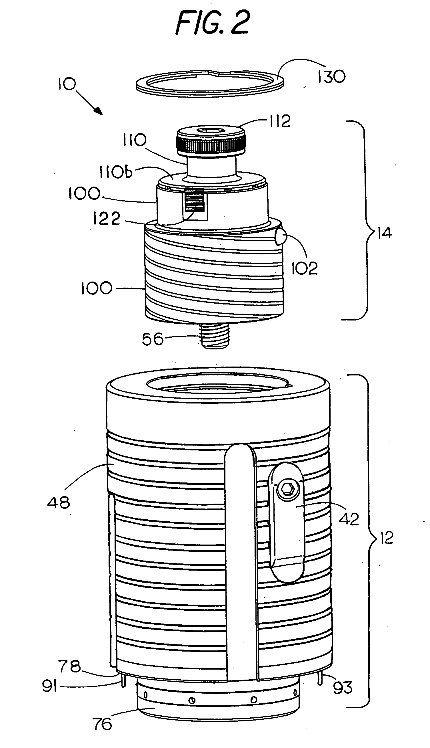
[0017]Refer now to the Figures and particularly to FIGS. 1-3. As shown best in FIGS. 1 and 2, the complete punch assembly indicated by the numeral 10 includes a punch housing and spring assembly 12 and a punch length adjustment subassembly 14 which fits into the top of the punch housing and spring assembly 12.

[0018]Refer now to FIG. 3 which illustrates the internal construction of the punch assembly 10. The punch assembly 10 includes a generally tubular punch housing or sleeve 48 of hardened and ground steel having a central longitudinal bore 50 that encloses the punch 45 and a punch retraction spring assembly 52 which in this case comprises a stack of disc or Belleville springs of annular configuration that during operation are compressed between a shoulder 54 at the bottom of the bore 50 and the lower end of a tubular punch head base 100 for retracting the punch 45 after each punch stroke. The unitary punch length adjustment subassembly 14 is made up of three major parts: a punch ...


PUM

PropertyMeasurementUnit
Lengthaaaaaaaaaa

Abstract

A punch assembly for a punch press has a punch housing with a punch that is slideably mounted for reciprocation along punch axis within the punch housing and at least one resilient member in the housing for yieldably biasing the punch upwardly in the housing along the punch axis. A punch length adjustment subassembly is provided in the punch housing. The subassembly has a base member that is slideable axially but non-rotatably mounted within the housing and a punch head member having an upper end that is positioned to be struck by a punch ram of a punch press for driving the punch downwardly to an operating position. The punch head is mounted for rotation on the punch axis relative to the base member but is held against axial movement relative to the base member. The punch head is operatively associated by a threaded length adjustment connection to the punch and a releasable stop member is connected between the punch head and the base member for preventing rotation of the punch head relative to the base member while the punch assembly is in operation on the punch press. The invention is also directed to the punch head subassembly per se as a retrofit insert to update existing punch assemblies for manual tooless punch length adjustment and tooless punch removal.

Description

FIELD OF THE INVENTION[0001]This invention relates to punching equipment to be used in a punch press and more particularly to tooless punch length adjustment.BACKGROUND OF THE INVENTION[0002]Many punch assemblies in commercial use such as the punch assembly described in U.S. Pat. No. 4,989,484 while otherwise very good require time-consuming disassembly using hand tools in order to remove the punch to sharpen the punch tip followed by reinstallation and readjustment of the length of the punch. This operation is labor intensive and, of course, lengthens the downtime of the equipment. Reduced press productivity is problematic particularly with respect to punch assemblies used in high-speed automated punch presses and punch assemblies that have a stripper for assisting in the removal of the workpiece from the punch tip. These punch assemblies require almost complete disassembly so that the punch can be removed for sharpening followed by reinstallation of the punch into the punch assemb...

Claims


Application Information

Patent Timeline
IPC IPC(8): B26D7/06
CPCB26D7/26B21D28/346B26F1/14B26D7/18Y10T83/2159Y10T83/9423Y10T83/9457Y10T83/9476
Inventor THIELGES, BRUCEBERRY, DAVID A.
Owner MATE PRECISION TOOLING
Why Eureka
Try Eureka