Method and Apparatus for Separation of Particles From a Flow of Gas

a technology of gas flow and separation method, applied in the direction of separation process, electrode cleaning, centrifuge, etc., can solve the problems of ineffective limitations, and ineffectiveness of electrostatic filter or cleaner, and achieve the effect of improving efficiency and capacity

Active Publication Date: 2009-10-29
GRIMALDI DEV AB
View PDF18 Cites 61 Cited by
  • Summary
  • Abstract
  • Description
  • Claims
  • Application Information

AI Technical Summary

Benefits of technology

[0005]An object of the present invention is to propose a method that improves the efficiency and capacity when separating off both large, heavy particles and also very small, light particles, either individually or in combination. In principle, this can be achieved according to the invention by the particles in the flow of gas being charged in an ionization step; by the flow of gas with the charged particles being caused to flow through a plurality of gaps between plate-shaped sedimentation surface elements on a rotor in a centrifugal separator, where an electrical field is generated by applying an electrical potential that is different to the potential of the particles across the adjacent sedimentation surface elements; by the particles being caused to be deposited on a face of the sedimentation surface elements during their passage through the gaps by means of at least an electrostatic attraction force; by the particles that are deposited on the sedimentation surface elements being caused to flow out towards the periphery of the sedimentation surface elements by the rotation of the rotor and from there to be thrown towards the inside of a casing surrounding the rotor; and by the particles that are trapped on the inside of the casing and the gas that is cleaned of particles being led out from the casing through separate outlets in the casing. By means of such a method, extremely small and light particles (smaller than approximately 1 μm), that are not able to be separated off using centrifugal force alone (“g-force separation”), are first caused to be deposited on the surface elements by electrostatic attraction forces, after which the accumulations of the particles on the surface elements can be thrown out towards the surrounding wall of the casing by the rotation of the rotor and are thereafter led out through the outlet for particles in the casing.
[0006]For the separation of both very small, light particles and heavier particles, it is particularly advantageous if the particles are caused to be deposited on a face of the sedimentation surface elements during their passage through the gaps by means of a simultaneous combined effect of a centrifugal force created by the rotation of the rotor and an electrostatic attraction force.

Problems solved by technology

However, in certain applications they can be less effective, for example for the separation of the very smallest and lightest particles in the flow of gas, for example particles smaller than approximately 1 μm.
In order to separate off extremely small and light particles from flows of gas, electrostatic filters or cleaners can be used, which, however, have limitations when it is a question of separating larger particles and handling larger quantities of particles.
A disadvantage with these separators is that the charged surfaces, on which particles are deposited, are stationary and quickly become coated to such an extent that the electrostatic forces are ineffective.
Accordingly, such separators cannot handle flows of gas with a high particle content.

Method used


Image

  • Method and Apparatus for Separation of Particles From a Flow of Gas
  • Method and Apparatus for Separation of Particles From a Flow of Gas
  • Method and Apparatus for Separation of Particles From a Flow of Gas

Examples


Embodiment Construction

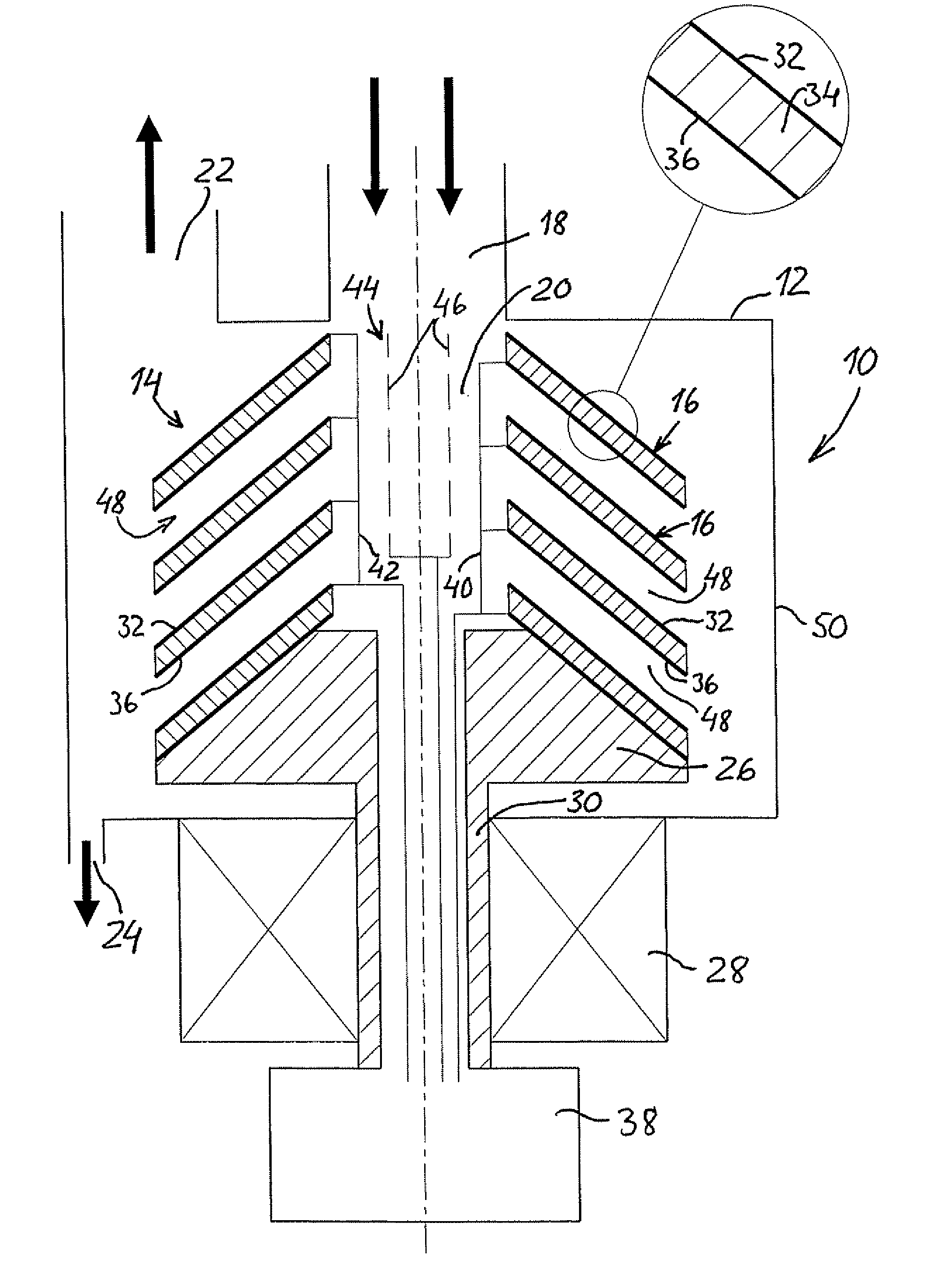
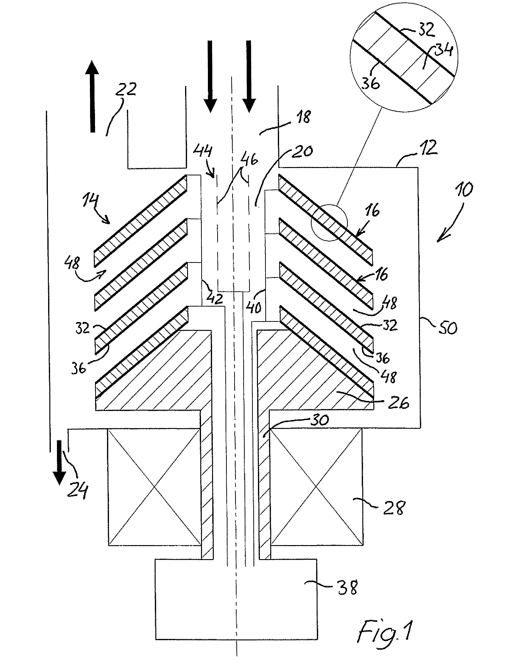
[0018]In FIG. 1, a first embodiment of a centrifugal separator according to the invention is indicated in general by the reference numeral 10, which centrifugal separator is intended to separate off electrostatically-charged, solid and / or liquid particles in a flow of gas by means of the simultaneous, combined effect of electrostatic attraction forces and centrifugal forces. The separator 10 comprises a stationary casing 12, in which a rotor 14 is mounted in such a way that it can rotate, which rotor has a plurality of sedimentation surface elements mounted on it in the form of a stack of concentric, conical, plate-shaped elements, so-called insert plates 16, the construction of which will be described in greater detail below. The casing 12 has an inlet 18 for the gas that is to be cleaned. The inlet 18 opens out concentrically into a central inlet shaft 20 in the rotor 14. The casing 12 has, in addition, an outlet 22 for the gas that has been cleaned in the centrifugal separator 10...


PUM

PropertyMeasurementUnit
voltageaaaaaaaaaa
electrical fieldaaaaaaaaaa
electrical potentialaaaaaaaaaa

Abstract

A method and apparatus for the separation of particles from a flow of gas, where both large, heavy and small, light particles can be separated off from the gas by means of the combined effect of an electrostatic attraction force and a centrifugal force in a centrifugal separator (10) of the type that comprises a rotor (14) that has a plurality of adjacent surface elements (16) with intermediate gas flow gaps (48) and that is mounted in such a way that it can rotate in a surrounding casing (12), which casing has an inlet (18) for unclean gas and an outlet (22) for clean gas and an outlet (24) for separated-of f particles. A charging unit (44) ionizes the particles upstream of the rotor (14). An electrical field is generated between adjacent surface elements (16) of the rotor in order to attract the ionized light particles towards a face of the surface elements by means of the electrostatic force. By means of the centrifugal force created by the rotor, the particles that have accumulated on the surface elements are thrown towards the inside of the casing and are led out through the outlet.

Description

TECHNICAL FIELD[0001]The present invention refers to a method for the separation of particles from a flow of gas. More specifically, the invention relates to a method for the separation of both very small, light particles and also larger, heavier particles from flows of gas. The invention also relates to an apparatus for carrying out such a method.BACKGROUND ART[0002]For the separation of particles from large flows of gas, various types of centrifugal separator are currently used. For example, WO 01 / 36103 and U.S. Pat. No. 3,234,716 describe centrifugal separators for cleaning gases containing particles, such as oil particles, dust, etc., where the separator comprises a rotor mounted in a stationary casing in such a way that it can rotate, with a stack of surface elements in the form of, for example, conical sedimentation plates (insert plates). Separators of this type are effective for the separation of particles within a wide range of particle sizes. This is due to the short sedim...

Claims


Application Information

Patent Timeline
Patent Type & Authority Applications(United States)
IPC IPC(8): B03C3/15B04B5/10B03C3/38B03C3/78
CPCB01D45/14B03C3/15B04B2005/125B04B5/10B04B5/12B03C3/366
Inventor FRANZEN, PETERINGE, CLAESLAGERSTEDT, TORGNY
Owner GRIMALDI DEV AB
Why Eureka
Try Eureka