High expansion foam fire-extinguishing system

a fire-extinguishing system and high-expansion foam technology, applied in fire rescue and other directions, can solve the problems of high possibility of foam generation, increase in cost, and difficulty in preventing foaming ratio degradation, and achieve the effect of reducing flow speed, preventing foaming ratio degradation, and facilitating generation

Inactive Publication Date: 2009-10-29
NOHMI BOSAI LTD
View PDF14 Cites 1 Cited by
  • Summary
  • Abstract
  • Description
  • Claims
  • Application Information

AI Technical Summary

Benefits of technology

[0025]In the present invention, as described above, the intermediate screen is arranged within the liquid droplet speed regulating region from the landing position at which the outer periphery of the emission pattern hits the inner wall of the foam generator body to the limit position at which the liquid droplets can pass through the mesh of the intermediate screen, and thus the foam solution radiated from the emission nozzle passes through the intermediate screen while being subjected to resistance to have an appropriate foam flow speed, and thereafter, impinges the foam forming screen. Thus, degradation of the foaming ratio can be prevented.
[0026]In the present invention, the length of the foam forming screen is in a range from the length substantially the same as the entire length of the foam generator body to the length of substantially two thirds of the entire length, and thus the distance from the emission nozzle to the foam forming screen becomes longer than in the related art. Thus, the force (emission energy) of the foam solution radiated from the emission nozzle drops before impinging the foam forming screen, and thus the foam solution impinges the foam forming screen with reduced flow speed, whereby the foam easily generates, and the degradation of the foaming ratio under smoke situation can be alleviated.
[0027]The foam forming screen of the present invention is folded so as to project towards the distal end side, and the distal end angle is set between 15° and 40°, and thus the length of the foam forming screen projecting from the distal end of the foam generator body becomes long compared to the related art. Thus, an area of the foam forming screen becomes large compared to the related art, and a contacting area of the foam solution and the foam forming screen increases, whereby the foaming ratio is enhanced.
[0028]At least two of the foam forming screens of the present invention are arranged in the height direction of the foam generator body, and thus a large area (contacting area) of the foam forming screen of triangular prism shape can be obtained without increasing the projection amount from the distal end of the foam generator body. Therefore, the foam generator can be miniaturized.
[0029]In the present invention, the distal end of the foam generator body is extended within the range from the length substantially the same as the entire length of the foam generator body to the length of substantially two thirds of the entire length, and thus the distance from the emission nozzle to the foam forming screen becomes longer than in the related art. Thus, the force (emission energy) of the foam solution radiated from the emission nozzle drops before impinging the foam forming screen, and thus the foam solution impinges the foam forming screen with reduced flow speed, whereby the foam easily generates, and the degradation of the foaming ratio under smoke situation can be alleviated.

Problems solved by technology

However, the method using outside air has problems such as increase in cost, because a duct needs to be passed through a building or a hole needs to be formed in a separating wall to arrange a foam generating machine (foam generator) to use the air outside.
In the related art, the force of the foam solution impinging the flow regulating part is weak because the space between the emission nozzle and the flow regulating part is long, and thus there is a high possibility that foam may generate at the stage of impinging the flow regulating part.
As a result, the foam may not be satisfactorily generated from the foam forming screen.
That is, the entire area of the foam forming screen cannot be used to generate foam because part of the mesh of the foam forming screen is blocked by the foam generated by the flow regulating part.
Thus, the foaming ratio may not be as designed.
As a solution for such problem, consideration is made in not arranging the flow regulating part, reducing the emission pressure to smaller than the standard set pressure and dropping an injection speed of the emission nozzle so that it is difficult for the liquid droplets of the foam solution to pass through the mesh.
Therefore, the amount of foam decreases and the desired amount of foam cannot be obtained within a predetermined time.

Method used


Image

  • High expansion foam fire-extinguishing system
  • High expansion foam fire-extinguishing system
  • High expansion foam fire-extinguishing system

Examples


first embodiment

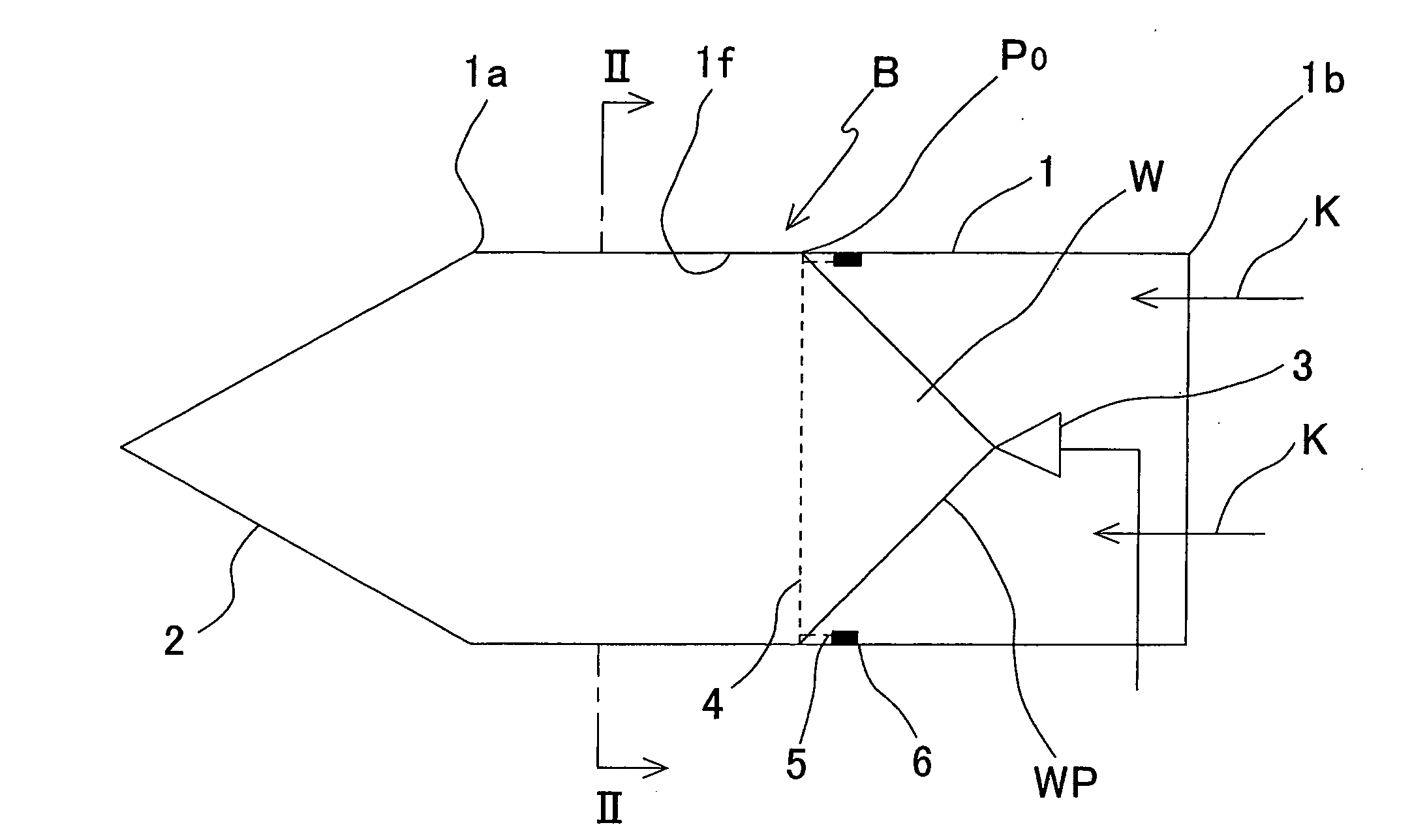
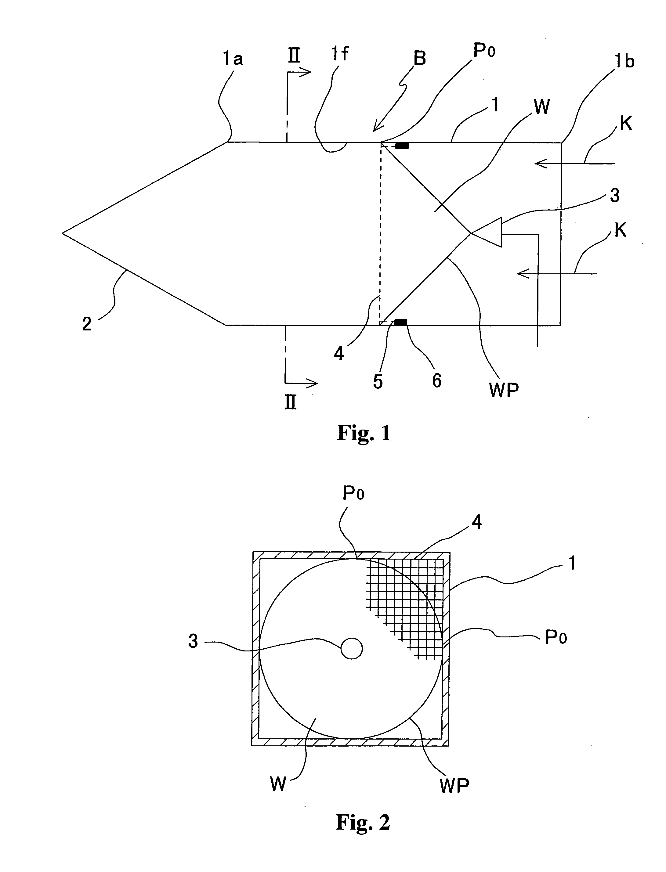
[0086]The first embodiment of the present invention is described with reference to FIGS. 1 to 3.

[0087]A foam generator B of a high expansion extinguishing facility is arranged in a room (chamber) of a fire monitoring section. The foam generator B is set to a foaming ratio of 500, for example.

[0088]The foam generator B includes a foam generator body 1 having a tubular shape such as having a cross-section of a square, and has the horizontal length L of 900 mm and the vertical length (height) H of 640 mm. The foam forming screen 2 is arranged at the distal end 1a side of the foam generator body 1. The emission nozzle 3 is built in on the back end 1b side of the foam generator body 1 at the position spaced apart by a predetermined distance such as 90 cm from the foam forming screen 2. The emission nozzle 3 radiates the foam solution W with an emission pattern WP spreading conically towards the foam forming screen 2.

[0089]The interior of the foam generator body 1 is partitioned by the in...

second embodiment

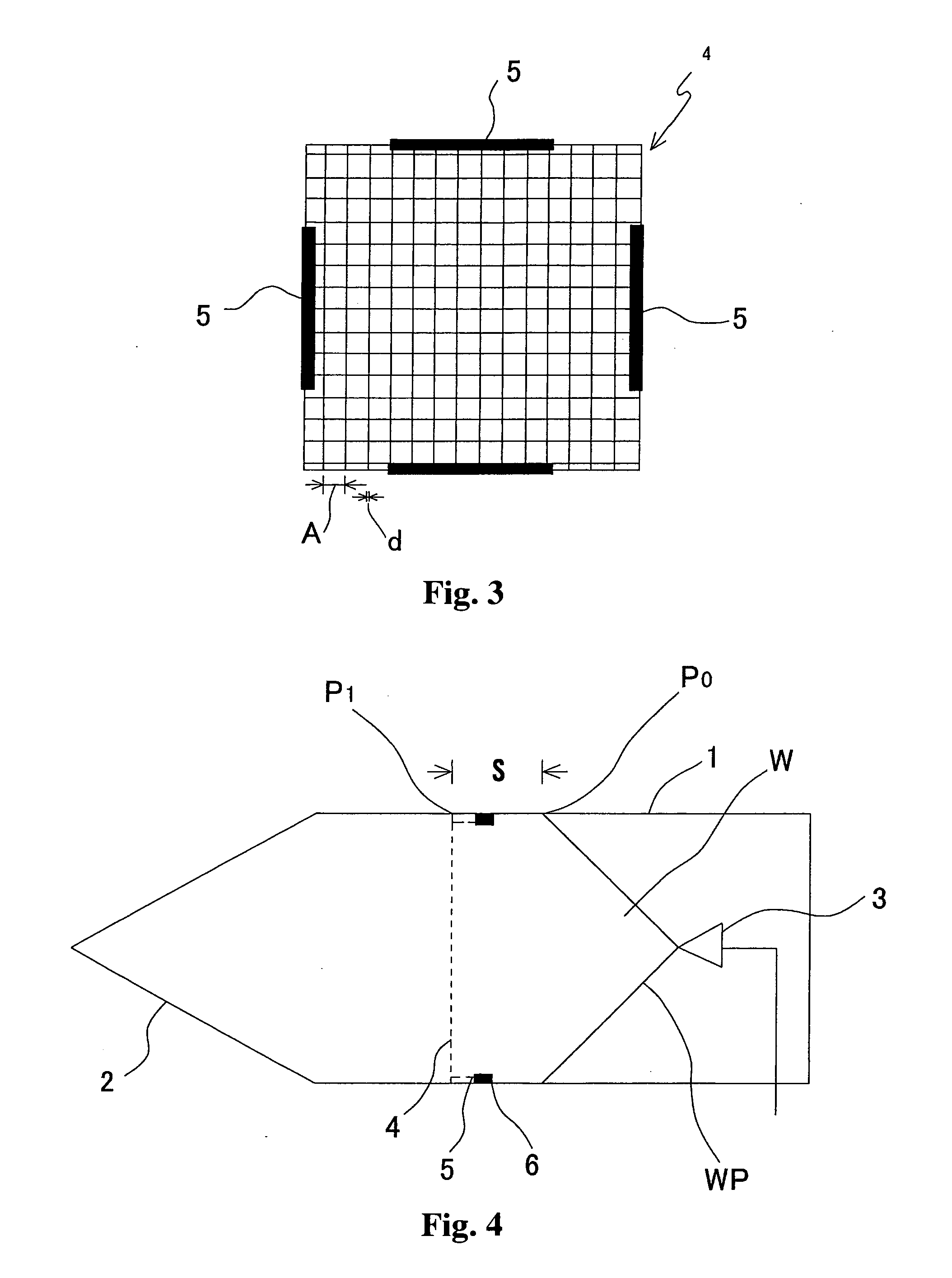
[0098]The second embodiment of the present invention is described with reference to FIG. 4, and the same reference symbols as illustrated in FIGS. 1 to 3 are given the same name and function. This embodiment differs from the first embodiment in the configuration of the foam generator (foam generator of this embodiment), and the other system configuration is substantially the same.

[0099]The difference between this embodiment and the first embodiment lies in the arrangement position of the intermediate screen 4. That is, the arrangement position P1 is the limit position in which the liquid droplets of the foam solution W radiated from the emission nozzle 3 can maintain the flow speed of passing through the mesh of the intermediate screen 4.

[0100]As described above, in this embodiment, the region from the landing position P0 in which the outer periphery of the emission pattern hits the inner wall of the foam generator body to the limit position P1 in which the liquid droplets can pass ...

third embodiment

[0102]The third embodiment of the present invention is described with reference to FIGS. 5 and 6, and the same reference symbols as illustrated in FIGS. 1 to 3 are given the same name and function. This embodiment differs from the first embodiment in the configuration of the foam generator (foam generator of this embodiment), and the other system configuration is substantially the same.

[0103]The difference between this embodiment and the first embodiment lies in that a plurality of emission nozzles 3 are arranged. The number of emission nozzles 3 is, for example, four, and such nozzles 4 are arranged in parallel, each distal end thereof being positioned on the same perpendicular surface.

[0104]The embodiments of the present invention are not limited to the above, and the intermediate screen 4 may be arranged tilted by a predetermined angle instead of being perpendicularly arranged. The tilt angle can be appropriately selected within the range of between 1 and 30 degrees.

[0105]In addi...


PUM


Abstract

In order to prevent foaming ratio from being degraded, there is provided a high expansion foam fire-extinguishing system (B) including: a foam generator body (1) formed to a tubular shape; a foam forming screen (2) arranged at a distal end (1a) side of the foam generator body (1); an emission nozzle (3) arranged at a back end (1b) side of an interior of the foam generator body, for radiating a foam solution (W) in an emission pattern (WP) that spreads in a conical shape towards the foam forming screen (2); and an intermediate screen (4) arranged between the foam forming screen (2) and the emission nozzle (3), in which the intermediate screen (4) is arranged in a liquid droplet speed regulating region from a landing position (P0) at which an outer periphery of the emission pattern (WP) hits an inner wall (1f) of the foam generator body to a limit position (P1) at which liquid droplets can pass through a mesh of the intermediate screen (4).

Description

BACKGROUND OF THE INVENTION[0001]1. Field of the Invention[0002]The present invention relates to a high expansion foam fire-extinguishing system used in a warehouse, a pit of an oil tank, a culvert of an oil industrial complex, a cabin, a hold, or the like.[0003]2. Description of the Related Art[0004]In a foam fire-extinguishing system, a foam solution is discharged from an emission nozzle and impinged on a foam forming screen to thereby suck air and generate foam, and the fire source is covered with such foam to extinguish the fire by smothering. The foam fire-extinguishing system in which a foaming ratio indicating a volume ratio of the foam solution and the generated foam is greater than or equal to 80 and smaller than 1,000 is referred to as a high expansion foam fire-extinguishing system.[0005]Great amount of air needs to be taken in from the upstream side of the emission nozzle in order to generate high expansion foam such as foam having the foaming ratio of greater than or eq...

Claims


Application Information

Patent Timeline
Patent Type & Authority Applications(United States)
IPC IPC(8): A62C31/12
CPCA62C5/02A62C31/12A62C3/06A62C3/10A62C31/02
Inventor MURATA, SHINJI
Owner NOHMI BOSAI LTD
Why Eureka
Try Eureka