Electromagnetic fuel injector for gaseous fuels with anti-wear stop device

a fuel injector and electromagnet technology, applied in the direction of fuel injectors, valve operating means/release devices, machines/engines, etc., can solve the problems of affecting the functional characteristics of the injector, affecting the braking action of the fuel on the anchor described above, and affecting the impact of the anchor against the fixed magnetic armature. , to achieve the effect of simple and cost-effective production

Active Publication Date: 2009-10-29
MARELLI EURO SPA
View PDF7 Cites 8 Cited by
  • Summary
  • Abstract
  • Description
  • Claims
  • Application Information

AI Technical Summary

Benefits of technology

[0011]The purpose of the present invention is to produce an electromagnetic fuel injector for gaseous fuels, in which said fuel injector overcomes the drawbacks described above, is simple and cost-effective to produce and in which the original functional characteristics are subject to limited alteration in time.

Problems solved by technology

On the other hand, when the fuel is gaseous, (for example methane or mixtures of propane and butane), the braking action of the fuel on the anchor described above is almost non-existent and the impact of the anchor against the fixed magnetic armature is therefore particularly violent.
Consequently, in fuel injectors for gaseous fuels the reciprocal contacting surfaces of the anchor and of the fixed magnetic armature are frequently subject to a considerable amount of wear with a subsequent loss of material which results in the lengthening of the anchor stroke and alters the functional characteristics of the injector.
Said wear is thus eventually the cause of significant variations in the functional characteristics of the injector, making proper injection control difficult, if not impossible, both in terms of the instant in which injection starts and in terms of the amount of fuel that is injected.
However, it has been observed that the element made of resilient material tends to wear out very quickly due to the effect of the anchor continuously impacting against the fixed magnetic armature, limiting the efficiency of this structural solution.
However, increasing the thickness of the component made of resilient material inevitably also increases the size of the magnetic gap between the anchor and the fixed magnetic armature (the resilient material is inevitably non-ferromagnetic) and thus makes it necessary to increase the number of ampere turns of the electromagnetic actuator with a subsequent increase in the cost, weight, overall dimensions and electric power consumption of the electromagnetic actuator.
However, it has been observed that by adjusting the pre-load of the closing spring it is possible to obtain an effective injection rate that is equal to the nominal injection rate, although this produces a significant fluctuation in the dynamic characteristics of the fuel injectors.
Said differences in the dynamic characteristics make it very complicated to control a fuel injector to perform very short injections (for instance as in the sequence of pilot injections preceding the main injection) in which said fuel injector is always in the transient state.

Method used


Image

  • Electromagnetic fuel injector for gaseous fuels with anti-wear stop device
  • Electromagnetic fuel injector for gaseous fuels with anti-wear stop device
  • Electromagnetic fuel injector for gaseous fuels with anti-wear stop device

Examples


Embodiment Construction

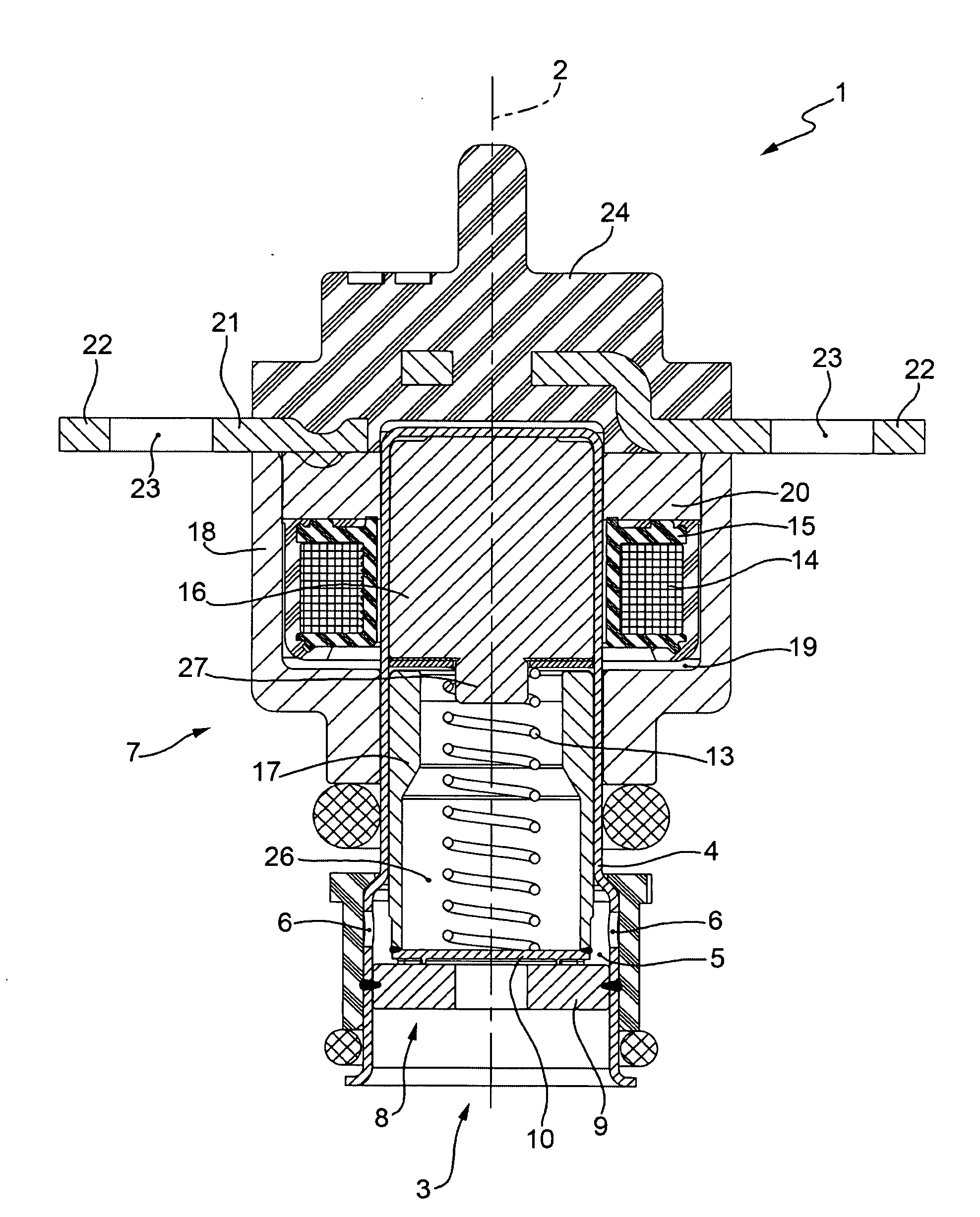
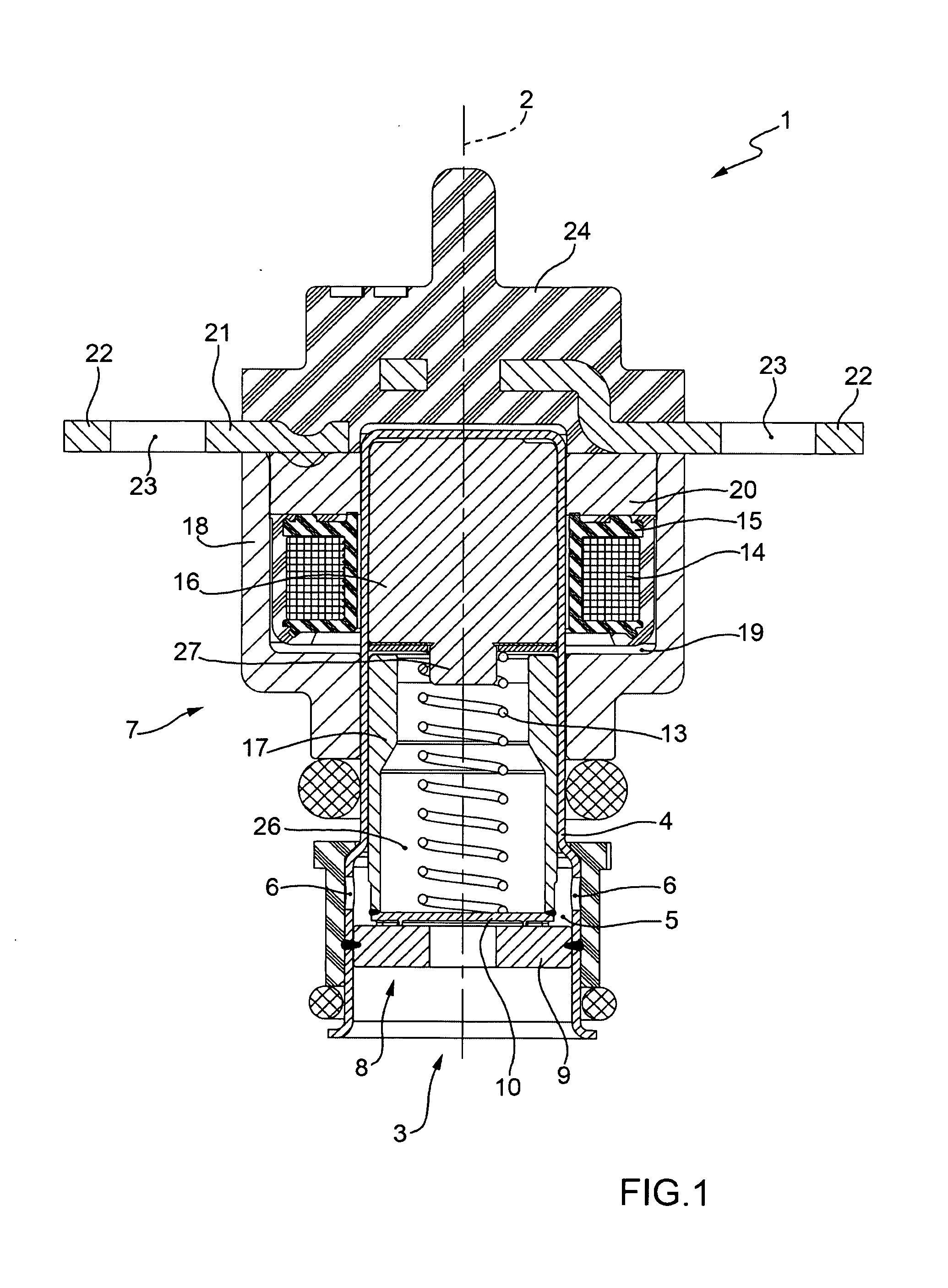
[0023]In FIG. 1, number 1 indicates a fuel injector as a whole, which is essentially cylindrically symmetrical about a longitudinal axis 2 and is controlled to inject fuel through an injection nozzle 3. As described more fully below, the fuel injector 1 receives the fuel radially (i.e. perpendicularly to the longitudinal axis 2) and injects the fuel axially (i.e. along the longitudinal axis 2).

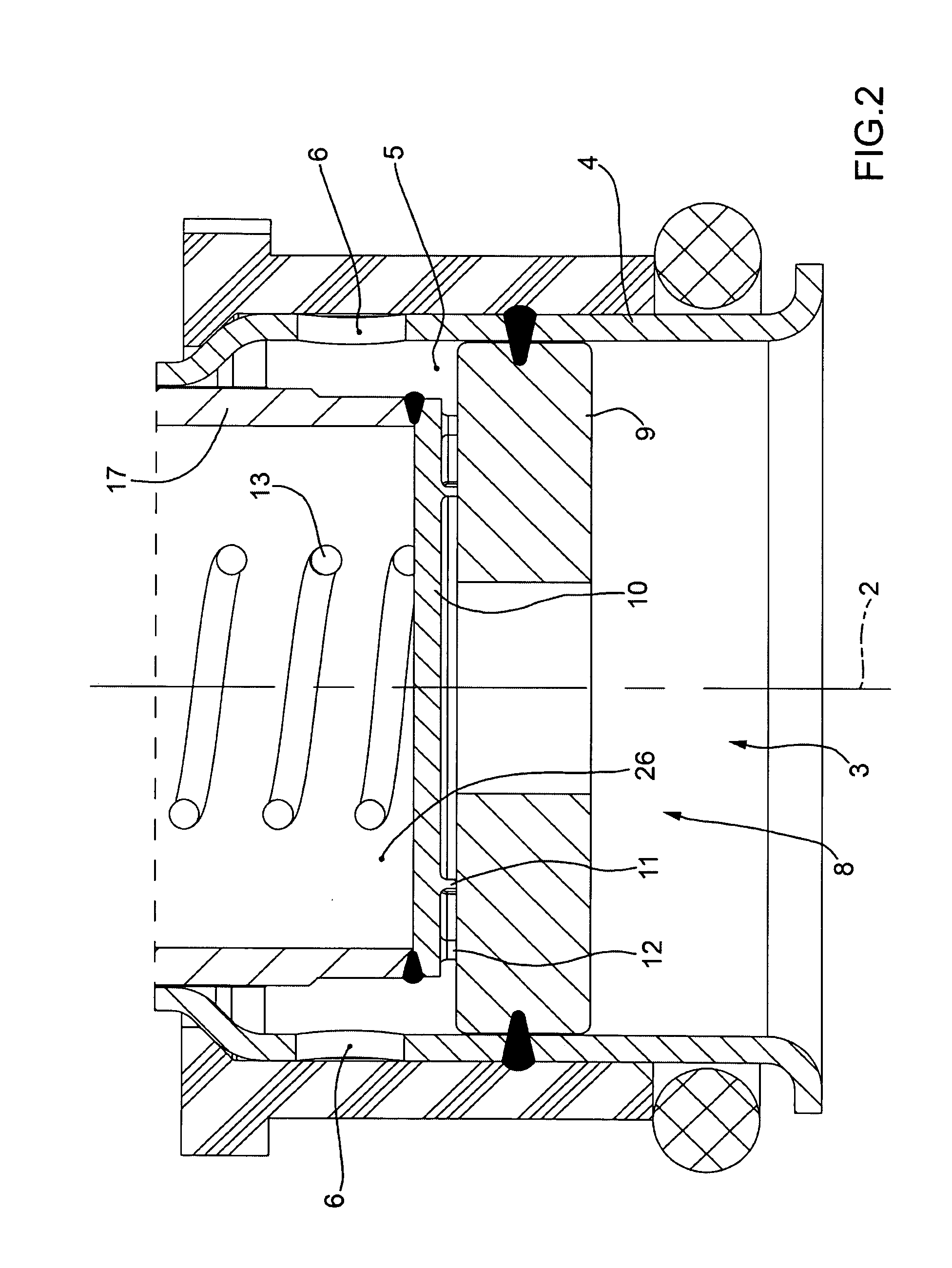
[0024]The fuel injector 1 comprises a tubular body 4, which is closed superiorly, is made by means of a drawing process out of ferromagnetic steel, and is provided with a cylindrical seat 5 the lower portion of which acts as a fuel duct. In particular, a lower portion of the tubular body 4 is provided with six radial through holes 6, which are arranged perpendicularly to the longitudinal axis 2, are distributed evenly about the longitudinal axis 2 and have the function of allowing the fuel to enter the cylindrical seat 5 in a radial manner.

[0025]The supporting body 4 houses an electromagnetic ...


PUM


Abstract

Electromagnetic fuel injector for gaseous fuels comprising: an injection nozzle controlled by an injection valve; a movable shutter to regulate the flow of fuel through the injection valve; an electromagnetic actuator, which is suitable to move the shutter between a closed position and an open position of the injection valve and comprises a fixed magnetic pole, a coil suitable to induce a magnetic flux in the magnetic pole, and a movable anchor suitable to be magnetically attracted by the magnetic pole; an absorption element, which is made of an amagnetic elastic material and is arranged between the magnetic pole and the anchor; and a protective element, which is made of a magnetic metal material having high surface hardness and is interposed between the absorption element and the anchor.

Description

TECHNICAL FIELD[0001]The present invention relates to an electromagnetic fuel injector for gaseous fuels.BACKGROUND ART[0002]An electromagnetic fuel injector comprises a tubular housing member inside which there is defined an injection chamber delimited at one end by an injection nozzle which is controlled by an injection valve governed by an electromagnetic actuator. The injection valve is provided with a shutter, which is rigidly connected to a movable anchor of the electromagnetic actuator so as to be moved under the action of said electromagnetic actuator between a closed position and an open position of the injection nozzle against the action of a closing spring that tends to hold the shutter in the closed position.[0003]The injection valve is normally closed due to the effect of the closing spring which pushes the shutter into the closed position, in which the shutter presses against a valve seat of the injection valve and the anchor is spaced apart from a fixed magnetic armat...

Claims


Application Information

Patent Timeline
Patent Type & Authority Applications(United States)
IPC IPC(8): F02M51/00F01L3/10
CPCF02M51/06F02M51/061F02M2200/306F02M61/20F02M61/168
Inventor DRAGONE, PASQUALECOBIANCHI, ANDREAVIGNOLI, MIRCO
Owner MARELLI EURO SPA
Why Eureka
Try Eureka