This helps you quickly interpret patents by identifying the three key elements:
Problems solved by technology
Method used
Benefits of technology
Benefits of technology
[0018]The present invention can realize high isolation of more than 140 dB in the same channel and the same polarization, i.e., co-channel and co-polarization by using three antenna devices.
[0019]Also, the technology of the present invention can be applied to an antenna for realizing co-channel, co-polarization and co-time bi-directional wireless communication of in a repeater, which includes wireless local area network (LAN), personal area network (PAN) and ultra-wideband (UWB), a Radio Frequency Identification (RFID) reader, and a mobile / satellite bi-directional communication system.
[0020]Also, the present invention can provide an antenna system and a relay system capable of simultaneous bi-directional communication in a co-channel which can form a wireless communication system, performance of which is remarkably improved in comparison with frequency division duplex (FDD) and time division duplex (TDD) methods in the respect of using existing frequencies.
Problems solved by technology
When the co-time, co-channel and co-polarization bi-directional communication technology is realized based on a conventional isolation antenna technology, there is a problem that it is difficult to identify a transmitting signal and a receiving signal from each other since a reflected wave for a transmitting signal and a receiving signal are simultaneously transmitted from a receiving end to a receiver.
However, since the former method is not the co-channel bi-directional communication method and the latter method is not the co-time bi-directional communication method, there is a problem that communication capacity is reduced.
Thus, there is a problem that the above technology is not proper as an antenna for a co-channel bi-directional communication in diverse mobile communication, local communication, a broadcasting repeater and a satellite communication field requiring high isolation in the same frequency.
Therefore, it is very difficult to realize a technology of an ultra isolation antenna which can be used in a co-channel bi-directional wireless communication system requiring ultra isolation more than 120 dB in the same polarization and same channel.
Method used
Image
Click on the blue label to locate the original text in one second.
Reading with bidirectional positioning of images and text.
Examples
first embodiment
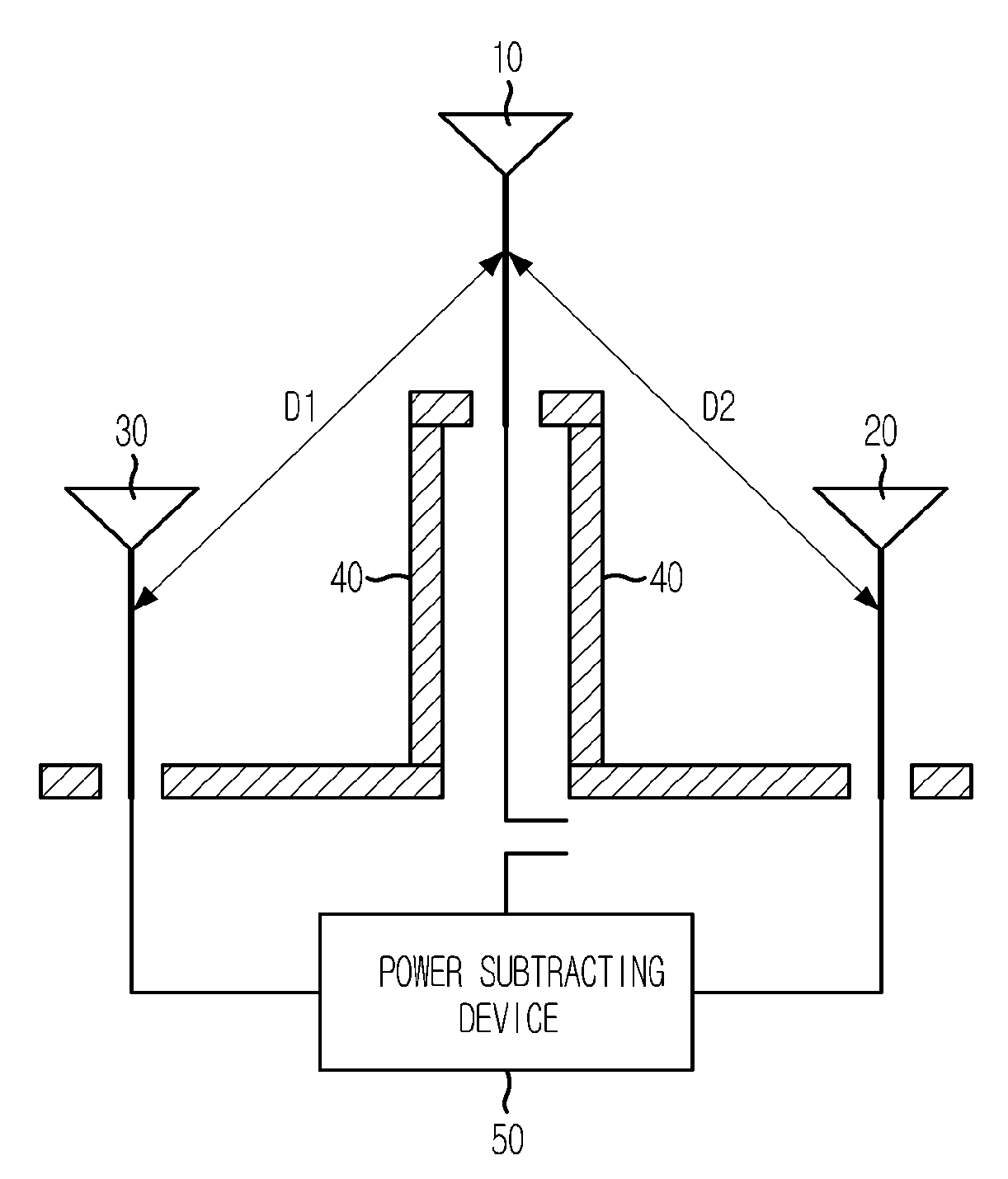
[0035]FIG. 1 is a diagram showing an ultra isolation antenna in accordance with the present invention.
[0036]As shown in FIG. 1, the ultra isolation antenna of the present invention includes a first antenna 10, a second antenna 20, a third antenna 30, a shielding unit 40 and a power subtracting device 50.
[0037]The configuration of the ultra isolation antenna of the present invention will be described in detail hereinafter.
[0038]In the ultra isolation antenna of the present invention, a center of the antenna is the first antenna 10, and the distances D1 and D2 from the first antenna to the second antenna 20 and the third antenna 30 are the same and symmetrical. The shielding unit 40 formed of a conductor or a shielding substance is symmetrically set up in the center between the second antenna 20 and the third antenna 30.
[0039]Herein, the signal transmitted from the first antenna 10 to the second antenna 20 and the third antenna 30 is removed by equally making the length of coaxial cab...
second embodiment
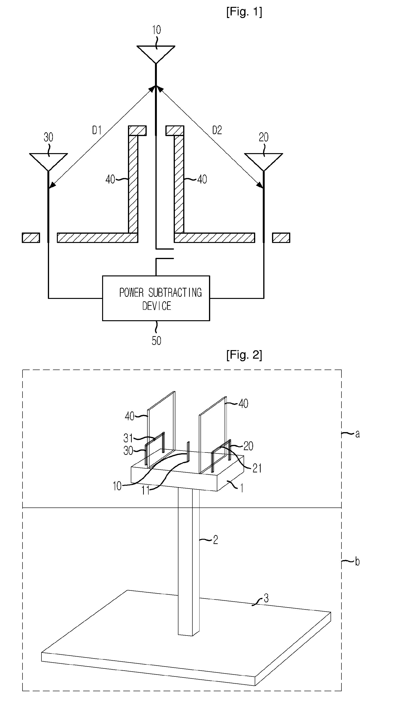
[0046]FIG. 2 is a perspective view showing an ultra isolation antenna in accordance with the present invention.
[0047]As shown in FIG. 2, the ultra isolation antenna of the present invention can be divided into an antenna device (a) for generating radiated electromagnetic wave or receiving electromagnetic wave and an antenna supporting unit (b) for supporting the antenna device.
[0048]In the antenna device (a), the first antenna 10 is set up in a monopole form in the center of a shielding box 1, which is sealed by an electric conductor such as gold, silver and aluminum and has a vacant space inside. The second antenna 20 and the third antenna 30 are symmetrically set up in the form of a loop antenna on the right and left sides based on the first antenna 10.
[0049]Both second antenna 20 and third antenna 30 are vertically set up as the soccer goalposts in the shielding box 1, and feeding units 21 and 31 are set up in the center of the loop antenna.
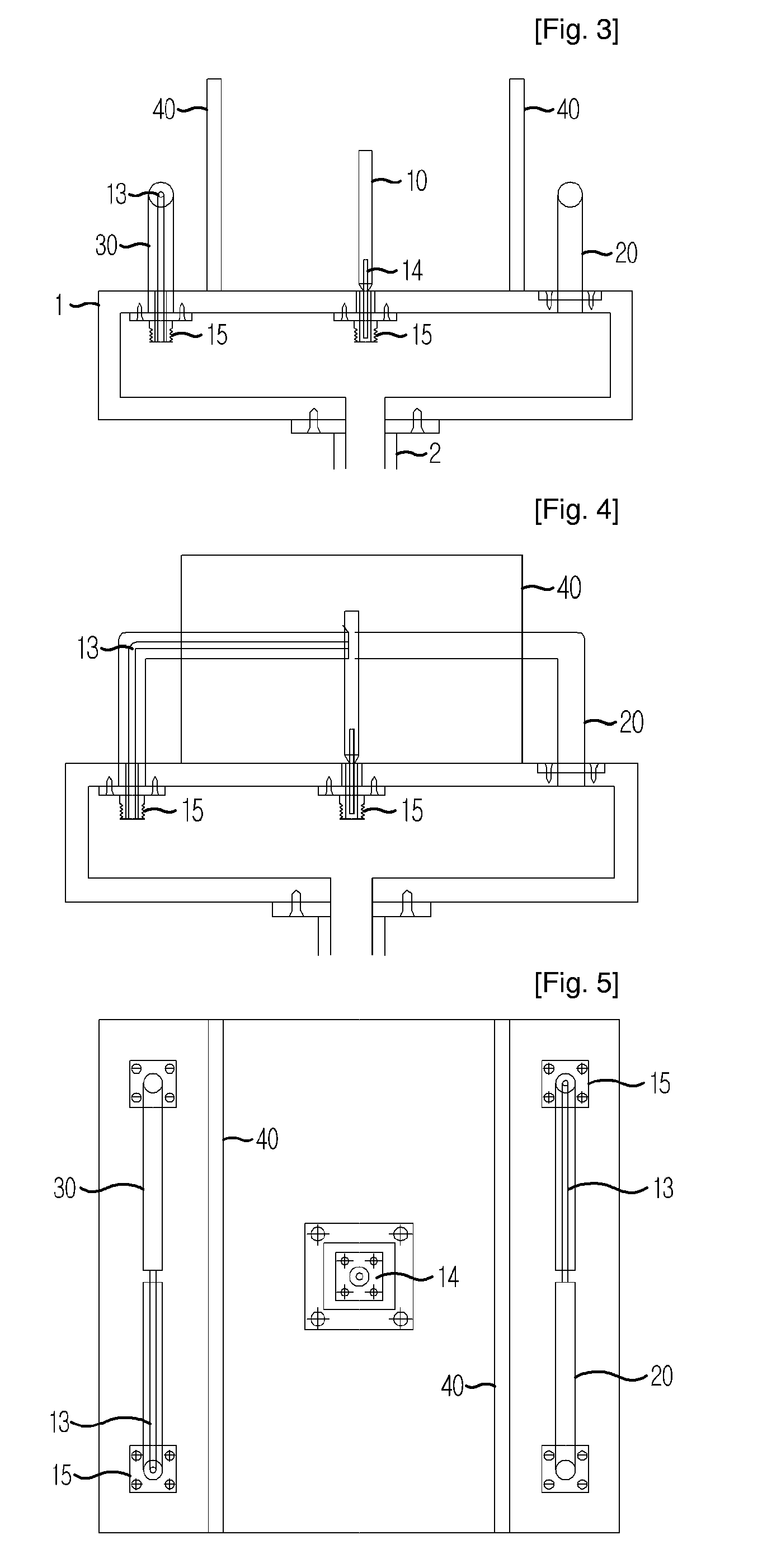
[0050]As shown in the drawing, a first ...
third embodiment
[0096]FIG. 10 is a cross-sectional plane view showing an ultra isolation antenna in accordance with the present invention.
[0097]As shown in FIG. 10, the third embodiment of the present invention shows a case that sets up feeding inside pins of the second and third antennas in the same connecting direction.
[0098]An electrical characteristic of a case connecting the second and third antennas with a power summating device of the third embodiment is the same as an electrical characteristic of a case connecting the second and third antennas with a power subtracting device of the second embodiment, and the same characteristic can be acquired by an opposite method.
PUM
Abstract
Provided is a transmitting / receiving isolation antenna that can perform wireless bi-directional communication in the co-channel, co-polarization and co-time by acquiring high isolation from transmitting and receiving antennas having co-time, co-channel and co-polarization and set up adjacently. The isolation antenna includes a first antenna; second and third antennas symmetrically positioned in the same distance from the first antenna; a shielding unit symmetrically positioned between the first and second antennas, and between the first and third antennas; and a signal removing unit for removing a signal transmitted from the first antenna to the second and third antennas.
Description
TECHNICAL FIELD[0001]The present invention relates to an ultra isolation antenna; and, more particularly, to a transmitting / receiving isolation antenna used in a co-channel bi-directional repeater.BACKGROUND ART[0002]A wireless technology for isolating transmitting / receiving signals from an antenna in a co-channel has been studied for a long time in a repeater field. Repeaters can be classified into a mono-directional repeater, in which receiving and transmitting directions are different from each other, and a bi-directional repeater, in which receiving and transmitting directions are the same.[0003]There should be a technological difference that antennas used in the co-channel mono-directional repeater are set up for different directivity, and antennas used in the bi-directional repeater are set up in such a manner that the entire or part of their directivity is overlapped.[0004]The bi-directional repeater is a bi-directional wireless communication system. The bi-directional repeat...
Claims
Application Information
Patent Timeline
Application Date:The date an application was filed.
Publication Date:The date a patent or application was officially published.
First Publication Date:The earliest publication date of a patent with the same application number.
Issue Date:Publication date of the patent grant document.
PCT Entry Date:The Entry date of PCT National Phase.
Estimated Expiry Date:The statutory expiry date of a patent right according to the Patent Law, and it is the longest term of protection that the patent right can achieve without the termination of the patent right due to other reasons(Term extension factor has been taken into account ).
Invalid Date:Actual expiry date is based on effective date or publication date of legal transaction data of invalid patent.

