

Transmit and receive antenna
- Summary
- Abstract
- Description
- Claims
- Application Information
AI Technical Summary
Benefits of technology
Problems solved by technology
Method used
Image

Examples
first embodiment
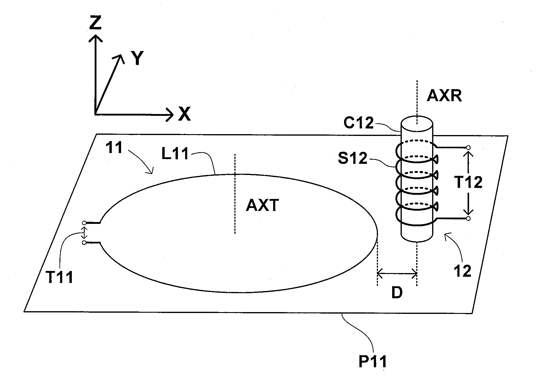
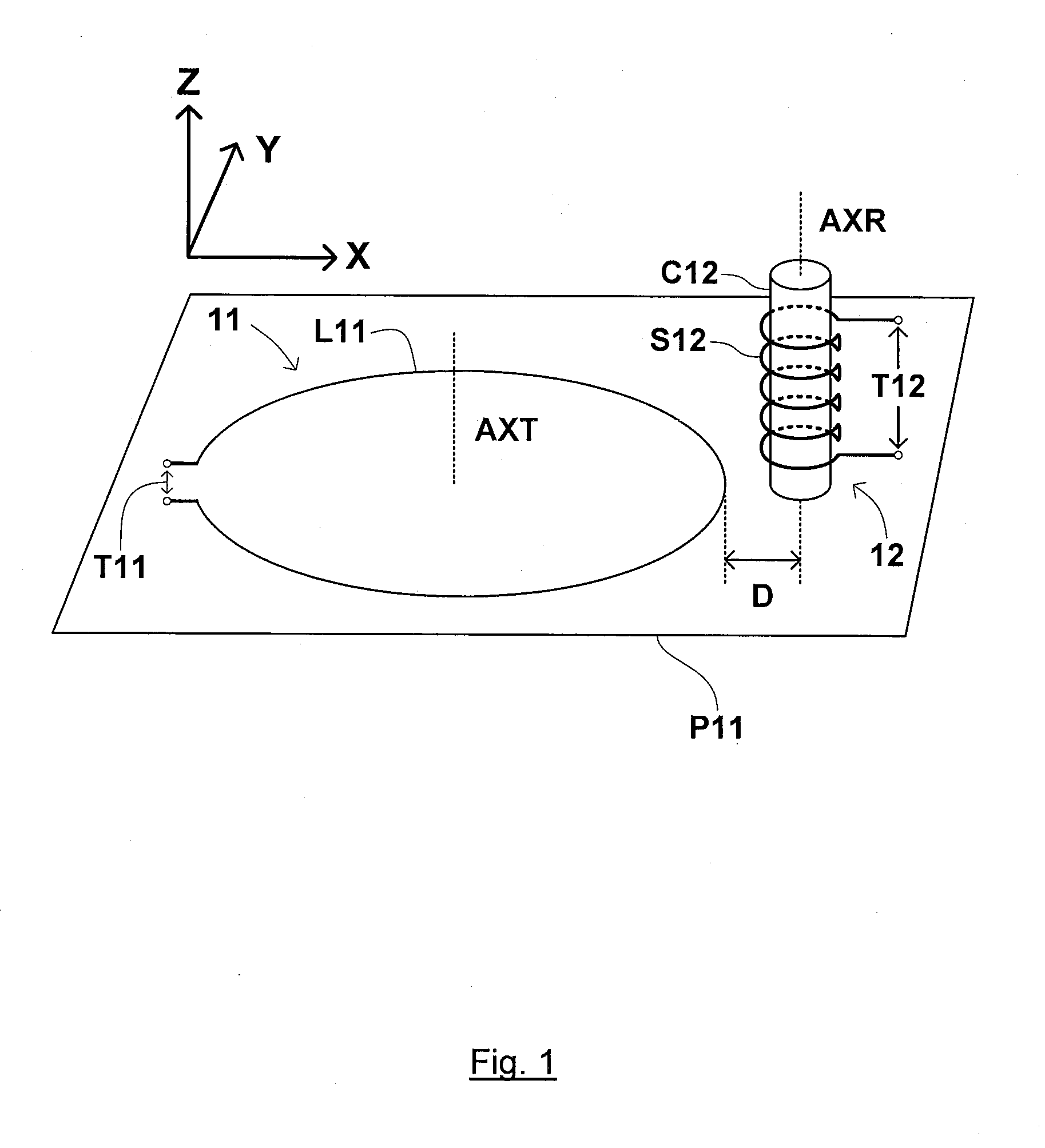
[0035]FIG. 1 shows a diagram illustrating a transmit / receive antenna of the present invention.
[0036]The transmit / receive antenna of FIG. 1 comprises TX section 11 and RX section 12, where TX section 11 and RX section 12 are located side by side. TX section 11 comprises magnetically coupled TX loop element L11 and TX input terminal T11 and RX section 12 comprises magnetically coupled RX solenoid element S12 wound on cylindrical core C12 and further comprises RX output terminal T12.
[0037]The transmit / receive antenna of FIG. 1 has two modes of operation, a TX mode and an RX mode. In the TX mode of operation, TX electrical signals fed to the TX input T11 of the TX section are output from TX section 11 as electromagnetic signals. In the RX mode of operation, RX electromagnetic signals incident on RX section 12 of the antenna produce an RX electrical signal at RX output terminal T12.
[0038]The transmit / receive antenna of FIG. 1 has a TX operating band and an RX operating band. Typically, t...
third embodiment
[0063]FIG. 6 shows a diagram illustrating the present invention.
[0064]The transmit / receive antenna of FIG. 6 comprises TX section 61 and RX section 62, where TX section 61 and RX section 62 are located near each other on one side of a plane P62. TX section 61 comprises magnetically coupled TX loop element L61 and TX input terminal T61. Magnetically coupled loop element L61 is formed of multiple windings of wire of an electrically conducting material. Magnetically coupled loop element L61 is orientated so that it lies in the XY plane and so that a central axis thereof AXT is parallel to the Z axis of a local co-ordinate system—shown in the top left hand portion of FIG. 6. RX section 62 comprises first magnetically coupled RX solenoid element S62 wound on cylindrical core C62 and connected to RX output terminal T62, second magnetically coupled RX solenoid element S63 wound on cylindrical core C63 and connected to RX output terminal T63 and further comprises third magnetically coupled ...
PUM
 Abstract
Description
Claims
Application Information