
Liquid crystal display

a liquid crystal display and display screen technology, applied in the field of liquid crystal displays, can solve the problems of reducing the brightness of the entire screen, blurring of borders of objects, and reducing the minimum brightness between frames, so as to solve image blur, no reduction in brightness, and no increase in power consumption

Active Publication Date: 2009-10-29
TRIVALE TECH
View PDF2 Cites 17 Cited by
  • Summary
  • Abstract
  • Description
  • Claims
  • Application Information

AI Technical Summary

Benefits of technology

[0012]A liquid crystal displays adopting a hold-type display scheme is provided which solves image blur in displaying moving images, with no reduction in brightness, no increase in power consumption and no increase in black brightness, while keeping costs low.
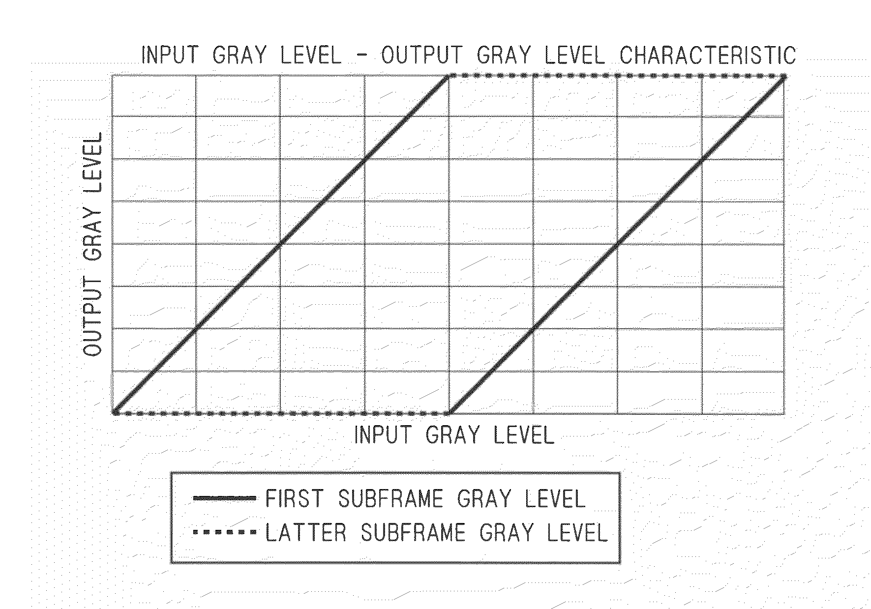
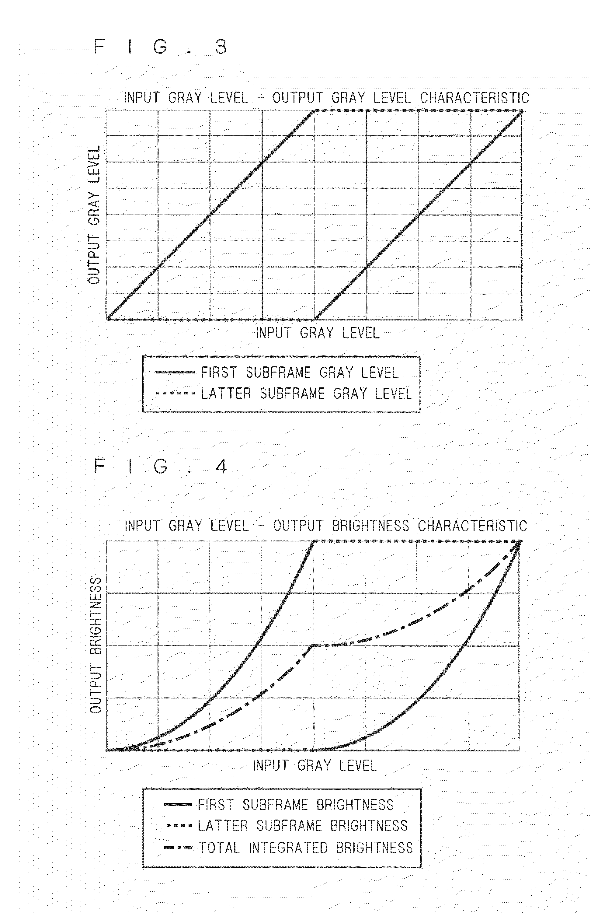
[0014]The liquid crystal displays described above divides input frame data into first subframe data and latter subframe data, and makes settings such that an average of integrated values of the output brightness of the first subframe and the output brightness of the latter subframe is equal to the target brightness of the input data, and the latter subframe data is created such that it includes four pieces of data including maximum output brightness data, minimum output brightness data, and arbitrary first and second brightness data respectively close to them, whereby image blur in displaying moving images is suppressed in a liquid crystal displays adopting a hold-type display scheme. Also, the reduction of brightness in the entire screen is suppressed by the use of the arbitrary brightness data respectively close to the maximum output brightness data and the minimum output brightness data as latter subframe data, together with the maximum output brightness data and the minimum output brightness data. Accordingly, there is no need to increase backlight brightness to deal with the reduction of brightness, and so the power consumption is not increased and the black brightness is not increased. Also, the conventional configuration can be used to obtain the effects above without a need to add special configuration to the liquid crystal displays, and so the circuit scale is not enlarged. Also, there is no need for increased frame memory capacity and higher-speed communication with the frame memory, and so no cost increase is needed.

Problems solved by technology

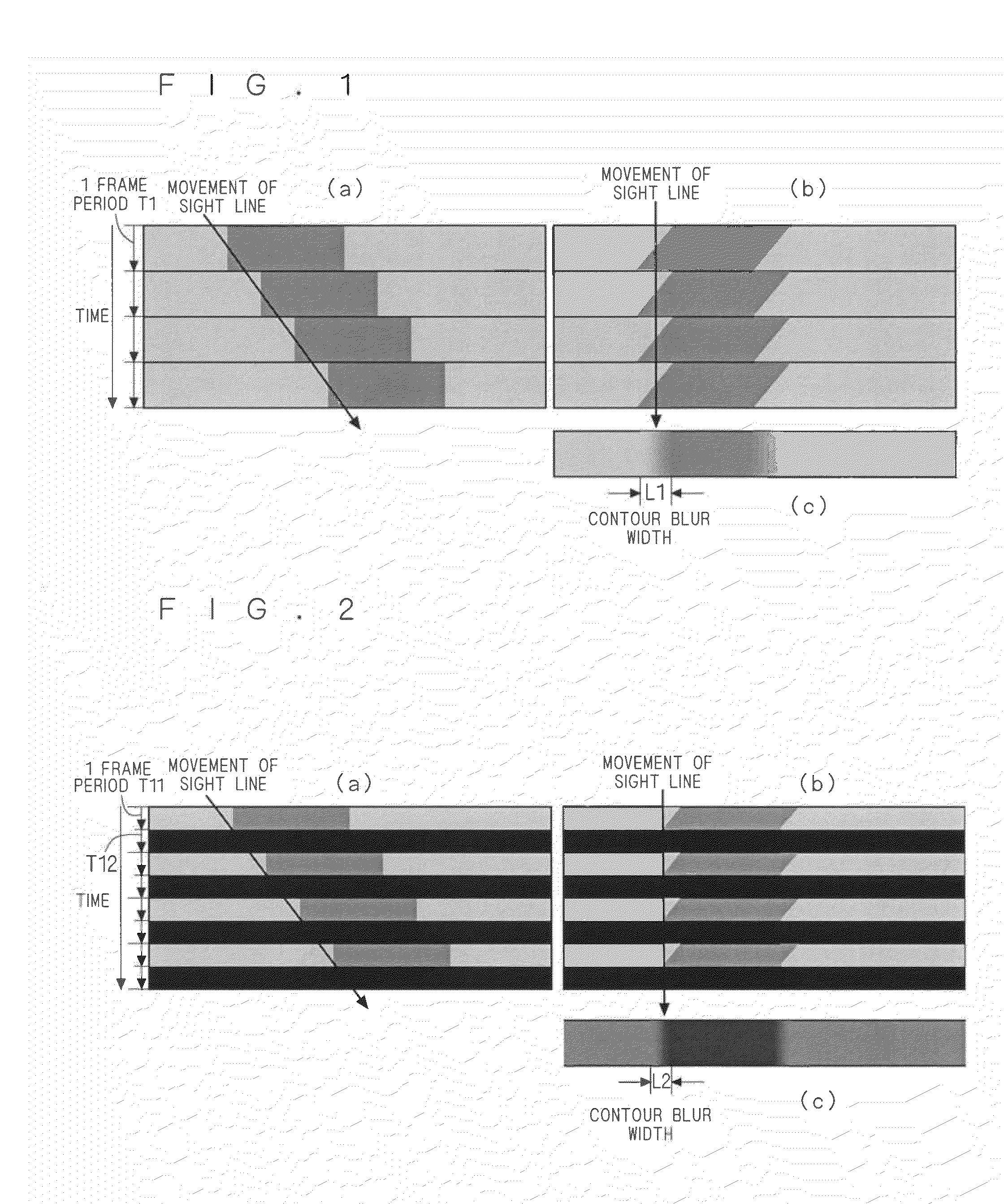
It is thus possible to achieve the target brightness within one frame by applying these methods, but the so-called hold-type display scheme has a peculiar problem that the boundaries of objects appear blurred when displaying moving images, because it provides no dark display between frames like the impulse-type display scheme.
However, while adopting the black frame insertion (black writing) scheme improves the display of moving images, inserting black of the minimum brightness between frames reduces the brightness in the entire screen.
There is a method that increases backlight brightness to solve the reduction of brightness, but it leads to problems such as increased power consumption and increased black brightness.
In this way, for the problem of image blur in displaying moving images, which is peculiar to the hold-type display scheme, various attempts have been made to solve the problem with no reduction in brightness, no increase in power consumption, and with no increase in black brightness, but such attempts involved problems leading to increased costs, such as increased circuit scale, need for increased frame memory capacity, and need for higher-speed communication with the frame memory.

Method used


Image

  • Liquid crystal display
  • Liquid crystal display
  • Liquid crystal display

Examples


first preferred embodiment

[0042]Now, a liquid crystal display according to a first preferred embodiment of the present invention will be described referring to FIGS. 8 to 14.

[0043]

[0044]FIG. 8 is a block diagram illustrating the circuit configuration of the entire liquid crystal display of the first preferred embodiment. As shown in FIG. 8, it includes a liquid crystal driving circuit (gate driver IC group) 2 for giving signals to the gate electrodes arranged in parallel to the longer sides of a rectangular liquid crystal panel 1, and a liquid crystal driving circuit (source driver IC group) 3 for giving signals to the source electrodes arranged in parallel to the shorter sides of the rectangular liquid crystal panel 1. A timing controller 4 is connected to the liquid crystal driving circuit 2 and the liquid crystal driving circuit 3 to control the liquid crystal driving circuit 2 and the liquid crystal driving circuit 3 on the basis of signal information from a data storage circuit (frame memory) 5.

[0045]FI...


PUM


Abstract

A data converter divides input data into first subframe data and latter subframe data, and the latter subframe data is given to a data serial-parallel converter and serial-parallel converted. The first subframe data is given to a line memory group, and given to an overdrive operation circuit after a given delay. The latter subframe data converted into parallel data is given to a line memory group, and given to a data parallel-serial converter after a given delay, where it is parallel-serial converted, and then it becomes output data after the first subframe data outputted from the overdrive operation circuit.

Description

BACKGROUND OF THE INVENTION[0001]1. Field of the Invention[0002]The present invention relates to liquid crystal displays, and particularly to a liquid crystal display that adopts a hold-type display scheme.[0003]2. Description of the Background Art[0004]In liquid crystal displays, tailing and after image may occur in the displayed moving images. When such troubles are due to the response time of the liquid crystals, there are known methods that improve the response time of the liquid crystal panel, or that use the overdrive function. In the overdrive function, when the gray level of the moving picture displayed on the liquid crystal panel does not achieve the target gray level, the voltage applied to the liquid crystal panel is temporarily raised to compensate for the lack of the applied voltage, so as to achieve the target gray level.[0005]It is thus possible to achieve the target brightness within one frame by applying these methods, but the so-called hold-type display scheme has ...

Claims


Application Information

Patent Timeline
IPC IPC(8): G09G3/36
CPCG09G3/2022G09G3/3648G09G2330/021G09G2320/0261G09G2320/0238
Inventor TAKAKI, JIRO
Owner TRIVALE TECH
Learn More