Method for rendering fluid

Inactive Publication Date: 2009-10-29
INSTITUTE FOR INFORMATION INDUSTRY
View PDF6 Cites 27 Cited by
  • Summary
  • Abstract
  • Description
  • Claims
  • Application Information

AI Technical Summary

Benefits of technology

[0008]Accordingly, the present invention is directed to a fluid rendering method, wherein fluid particles are rendered as two-dimensional metaballs according to state information such as the positions of the fluid particles and the interactions between the fluid particles and a terrain or a dynamic objects such that a splash effect of the fluid can be simulated.
[0022]In the present invention, a height field is adopted for representing a terrain and dynamic objects in the region through which the fluid flows, the approximate direction along which the fluid particles flow is then obtained by calculating the gradient of the height field, and collisions between the fluid particles and the terrain or the dynamic objects are detected, so as to generate visual effects such as splashes and foams. Moreover, in the present invention, the mergence and separation of water drops are simulated by using two-dimensional metaballs and the thickness and depth of the fluid are simulated with multilayer textures, so that the visual effect of realistic fluid can be achieved.

Problems solved by technology

Due to the huge quantity of calculations to be carried out, an existing technique for rendering fluid and the interaction between fluid and terrain or dynamic objects (dynamic obstacles) usually requires a lot of calculations and very high production cost in order to achieve a good simulation effect.
However, by using the method described above, the splashed water drops, the splatting, or rapid current caused by collisions between the fluid and dynamic obstacles or the terrain cannot be presented.
Thereby, the fluid simulated does not look realistic enough.
However, such a method can only be applied to the rendering of calm and slow fluid but still cannot actually simulate aforementioned splash effects such as water drops, splatting, or rapid current.

Method used


Image

  • Method for rendering fluid
  • Method for rendering fluid
  • Method for rendering fluid

Examples


Embodiment Construction

[0035]Reference will now be made in detail to the present preferred embodiments of the invention, examples of which are illustrated in the accompanying drawings. Wherever possible, the same reference numbers are used in the drawings and the description to refer to the same or like parts.

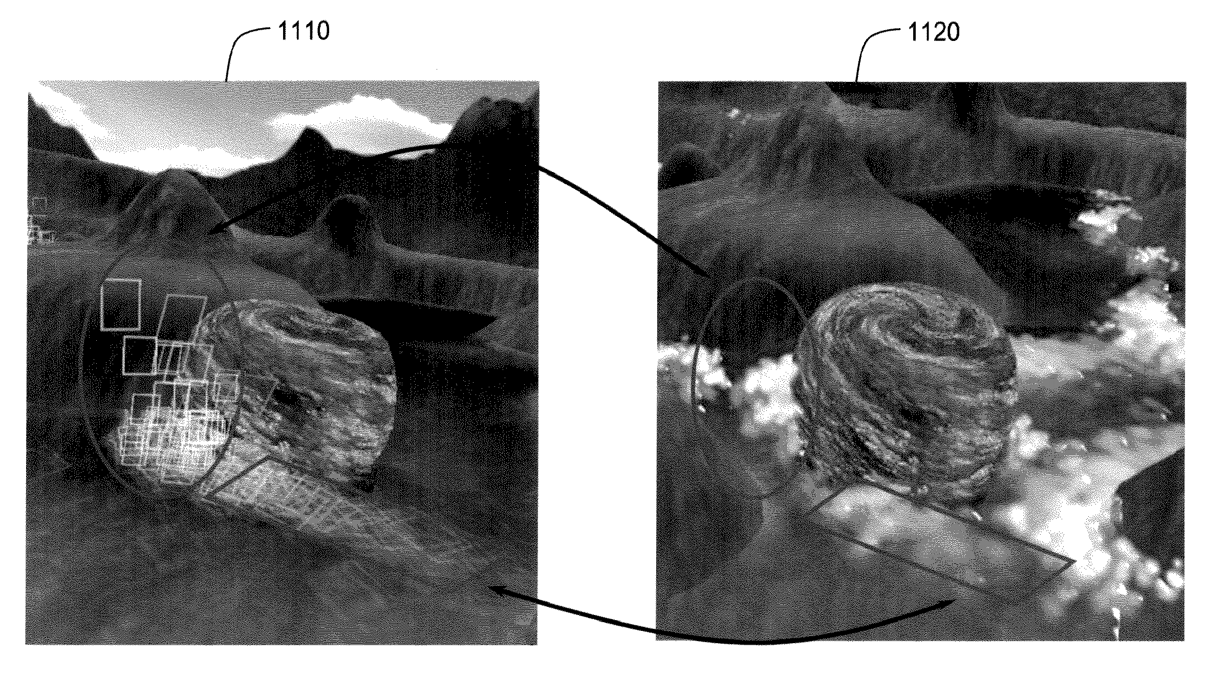
[0036]In the present invention, different visual effects such as rapid current and splashes or foams generated by collisions between a fluid and a terrain or dynamic objects are correctly and quickly simulated based on physical principles and the interactions between the fluid and the irregular terrain or dynamic objects. Accordingly, the present invention provides a fluid rendering method based on foregoing concept. Embodiments of the present invention will be described below with reference to accompanying drawings. It should be noted herein that the dynamic objects as described above and hereinafter are defined as the obstacles that may interact with the fluid particles in the flow path of the flui...


PUM


Abstract

A method for rendering fluid is provided. First, state information of a plurality of fluid particles is provided, wherein the state information records whether the fluid particles are located above or under a fluid surface and the interactions between the fluid particles and a terrain or the dynamic objects. Then, whether to render the fluid particles in a direction facing a viewer or in a direction parallel to the flow direction is determined according to the information that whether the fluid particles are located above or under the fluid surface. Next, the fluid particles are rendered as a plurality of two-dimensional metaballs according to the interactions between the fluid particles and the terrain or the dynamic objects, and these metaballs are stacked to reconstruct the fluid.

Description

CROSS-REFERENCE TO RELATED APPLICATION[0001]This application claims the priority benefit of Taiwan application serial no. 97115577, filed on Apr. 28, 2008. The entirety of the above-mentioned patent application is hereby incorporated by reference herein and made a part of specification.BACKGROUND OF THE INVENTION[0002]1. Field of the Invention[0003]The present invention generally relates to a graphics rendering method, and in particular, to a fluid rendering method.[0004]2. Description of Related Art[0005]Due to the huge quantity of calculations to be carried out, an existing technique for rendering fluid and the interaction between fluid and terrain or dynamic objects (dynamic obstacles) usually requires a lot of calculations and very high production cost in order to achieve a good simulation effect. In particular, as to a technique which needs to simulate and render graphics in real-time, the interaction between the fluid and the terrain is usually ignored, and accordingly the qua...

Claims


Application Information

Patent Timeline
IPC IPC(8): G06T15/70G06T13/60G06T15/20
CPCG06T13/60G06T2210/24G06T15/205
Inventor CHANG, HSIANG-YUNCHANG, CHUN-FACHEN, LI-CHENG
Owner INSTITUTE FOR INFORMATION INDUSTRY
Why Eureka
Try Eureka