Structure and method to polarize an electromagnetic wave

a technology of electromagnetic waves and polarization methods, applied in the field of polarization of electromagnetic waves, can solve the problems of reducing light intensity by a large amount, unable to achieve polarization of light, and not being suitable for certain applications

Inactive Publication Date: 2009-10-29
IND TECH RES INST
View PDF7 Cites 15 Cited by
  • Summary
  • Abstract
  • Description
  • Claims
  • Application Information

AI Technical Summary

Problems solved by technology

Since the electric field direction of a non-polarized EM wave is not unique in any direction while propagating in space, a non-polarized EM wave is not suitable for (or limited to) certain applications.
However, the structure used to polarize light can be achieved only after good design, and many manufacturers now continue to develop more efficient, lower cost, and easily-fabricated EM wave polarizing structure.
The conventional polarizer reduces light intensity by more than a half while light propagates through it; 2. As for LED combined with a polarizer, the medium interfaces will cause multiple Fresnel reflection loss; 3. The design and fabrication process of a conventional polarizer are excessively complex and expensive.

Method used


Image

  • Structure and method to polarize an electromagnetic wave
  • Structure and method to polarize an electromagnetic wave
  • Structure and method to polarize an electromagnetic wave

Examples


Embodiment Construction

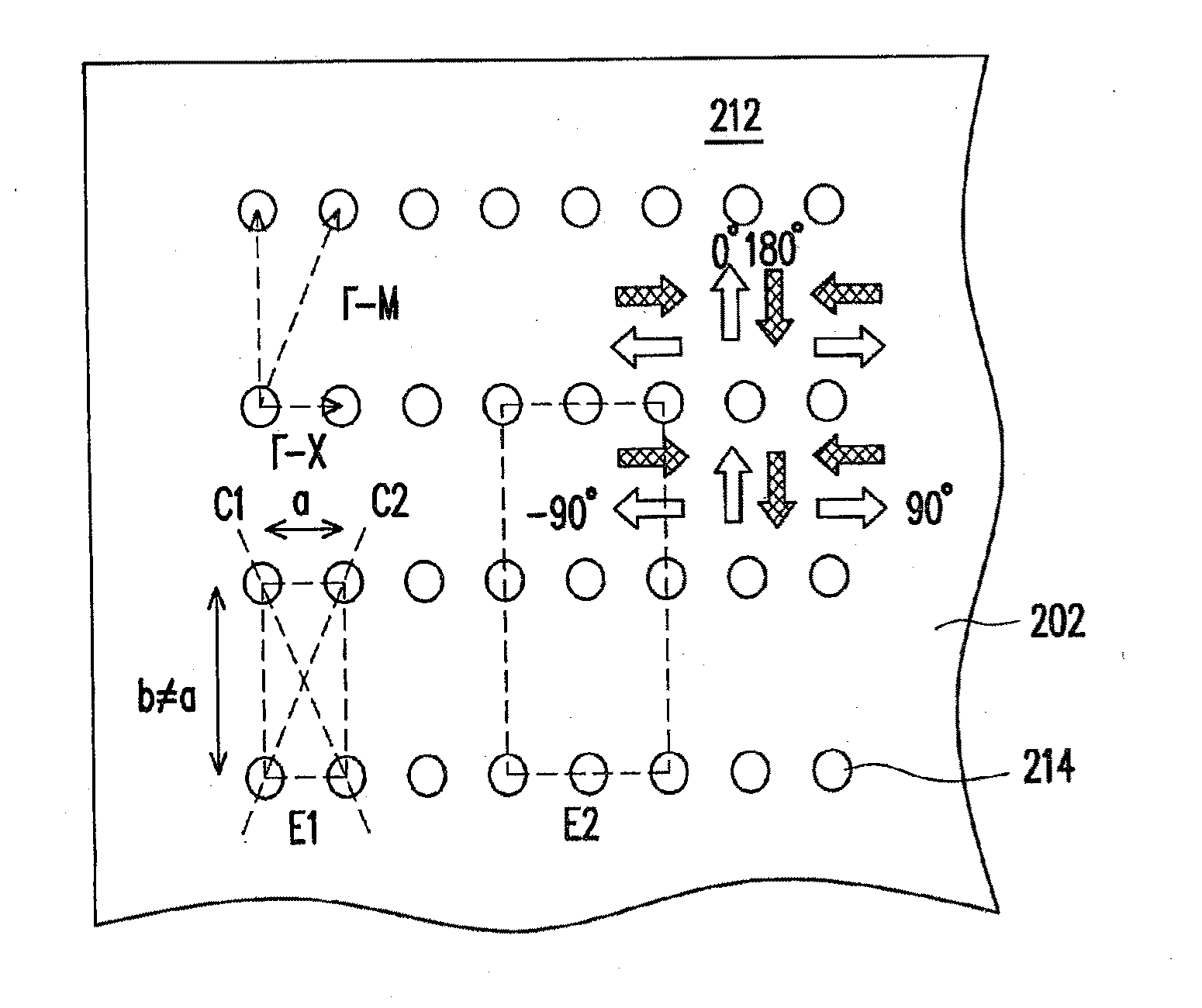
[0040]According to electromagnetic wave theory, a non-polarized electromagnetic wave (EM wave) can decompose into any two independent orthogonal components: for instance, a TE mode and a TM mode, which correspond to two mutually perpendicular eigen modes with electric field orthogonal to each other. If an EM wave only includes TE mode component or TM mode component, the EM wave is polarized. The EM wave mentioned herein includes visible light. A non-polarized EM wave can become polarized in TM-mode or in TE-mode if it interacts with a special device or materials. The EM wave polarization mechanism for a non-polarized EM wave will be described below. Thereafter, a LED structure of the invention will be taken as an example for description. However, the invention is not limited to this example. It also works for a resonant cavity light emitting diode (RCLED), a vertical cavity surface emitting laser (VCSEL), organic light emitting diode (OLED), or polymeric light emitting diode (PLED)....


PUM


Abstract

The EM polarizing structure, which contains a two dimensional planar variation structure, having medium nodes regularly distributed as a two dimensional planar photonic unit lattice cell array on a plane. Each of said unit photonic lattice cells has an operation axis and is identical at each lattice point, which passes a diagonal of said unit photonic lattice cell. The medium nodes within each said planar photonic unit lattice cell are distributed asymmetrical with respect to said operation axis direction and identical at each lattice point. The said EM polarizing structure is used to modulate an input EM wave around an operation frequency of the photonic band associated with said EM wave polarizing structure. Thus a corresponding output EM wave becomes polarized. Moreover, said electromagnetic (EM) wave polarizing structure can be integrated with an EM wave emitting source. Thus an output EM) wave from said device is polarized.

Description

CROSS-REFERENCE TO RELATED APPLICATION[0001]This is a continuation-in-part application of and claims the priority benefit of patent application Ser. No. 11 / 439,478, filed on May 22, 2006, which claims the priority benefit of Taiwan application serial no. 94139860, filed on Nov. 14, 2005. The entirety of each of the above-mentioned patent applications is hereby incorporated by reference herein and made a part of this specification.BACKGROUND OF THE INVENTION[0002]1. Field of Invention[0003]The invention relates to an electromagnetic (EM) wave polarizing technique, more particularly, to an asymmetric two-dimensional photonic crystal unit cell array structure and method for generating a non-in-plane polarized EM wave.[0004]2. Description of Related Art[0005]Generally, most of electromagnetic (EM) waves in nature exist in a non-polarized state. Herein, light refers to an EM wave at around a frequency within a specific range. Since the electric field direction of a non-polarized EM wave ...

Claims


Application Information

Patent Timeline
Patent Type & Authority Applications(United States)
IPC IPC(8): G02B5/30G02B1/08
CPCG02B5/3058H01L33/02H01L2933/0083H01S2301/18H01S5/18355H01S5/187H01S2301/14H01S5/105H01S5/11
Inventor WANG, JIH-FU TREVORCHI, JIM-YONG
Owner IND TECH RES INST
Why Eureka
Try Eureka