Method and system for congestion marking

a congestion marking and packet switching technology, applied in data switching networks, frequency-division multiplexes, instruments, etc., can solve the problem that feeding congestion information derived from mpls into ip does not provide the same early congestion detection

Inactive Publication Date: 2009-10-29
BRITISH TELECOMM PLC
View PDF10 Cites 92 Cited by
  • Summary
  • Abstract
  • Description
  • Claims
  • Application Information

AI Technical Summary

Benefits of technology

[0034]According to one aspect the invention provides a method of determining congestion information in a data network, comprising the steps: receiving, at an upstream element having a higher layer in the protocol stack, lower layer congestion information from a network element at a lower layer in the stack, the congestion information relating to data traffic congestion occurring at a downstream element in the flow, the downstream element being within the lower layer; determining higher layer congestion information to be used in the higher layer, in dependence on the lower layer congestion information; and applying the higher layer congestion information to data traffic in the higher layer. As a result, a higher layer congestion control scheme can incorporate information from a lower layer, thus allowing for congestion control to be performed earlier than may otherwise be the case.
[0041]In preferred embodiments the network layer congestion information is determined in dependence on a probability function with respect to virtual queue size in the network layer element, wherein the probability function is adapted in dependence on the data link layer congestion information. Adaptation of the marking probability function allows for relatively straightforward translation of the data link layer congestion information into the network layer congestion information.

Problems solved by technology

However, as discussed, MPLS is not a true data link layer protocol, instead being directed at providing simpler switching, and requires another data link layer protocol underneath to perform the actual data transmission between switches.
Thus feeding congestion information derived from MPLS into IP does not provide the same early congestion detection as can be obtained from congestion information obtained within the real link layer from looking at the link layer traffic queues.

Method used


Image

  • Method and system for congestion marking
  • Method and system for congestion marking
  • Method and system for congestion marking

Examples


Embodiment Construction

[0062]Embodiments of the present invention will now be described with respect to the drawings.

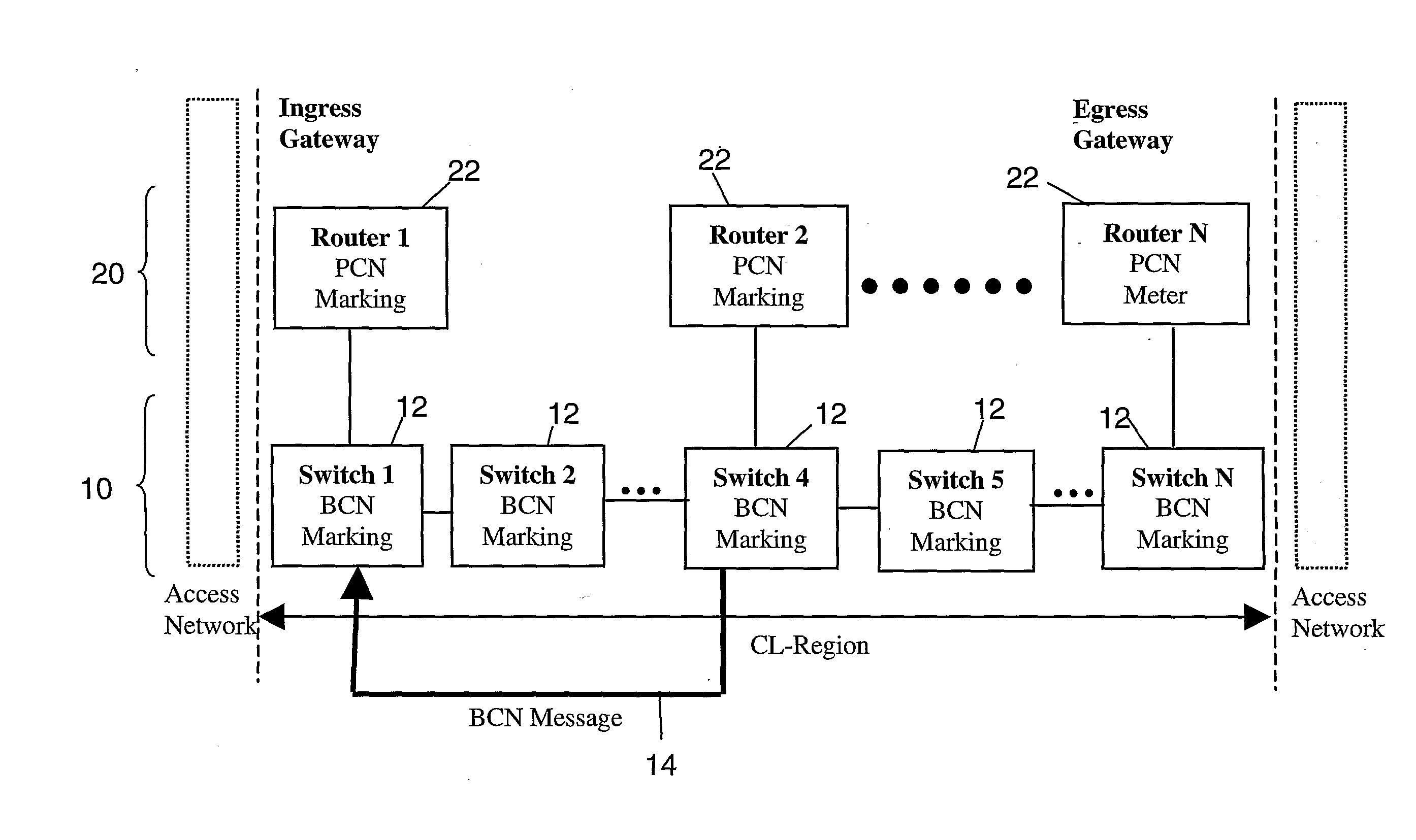
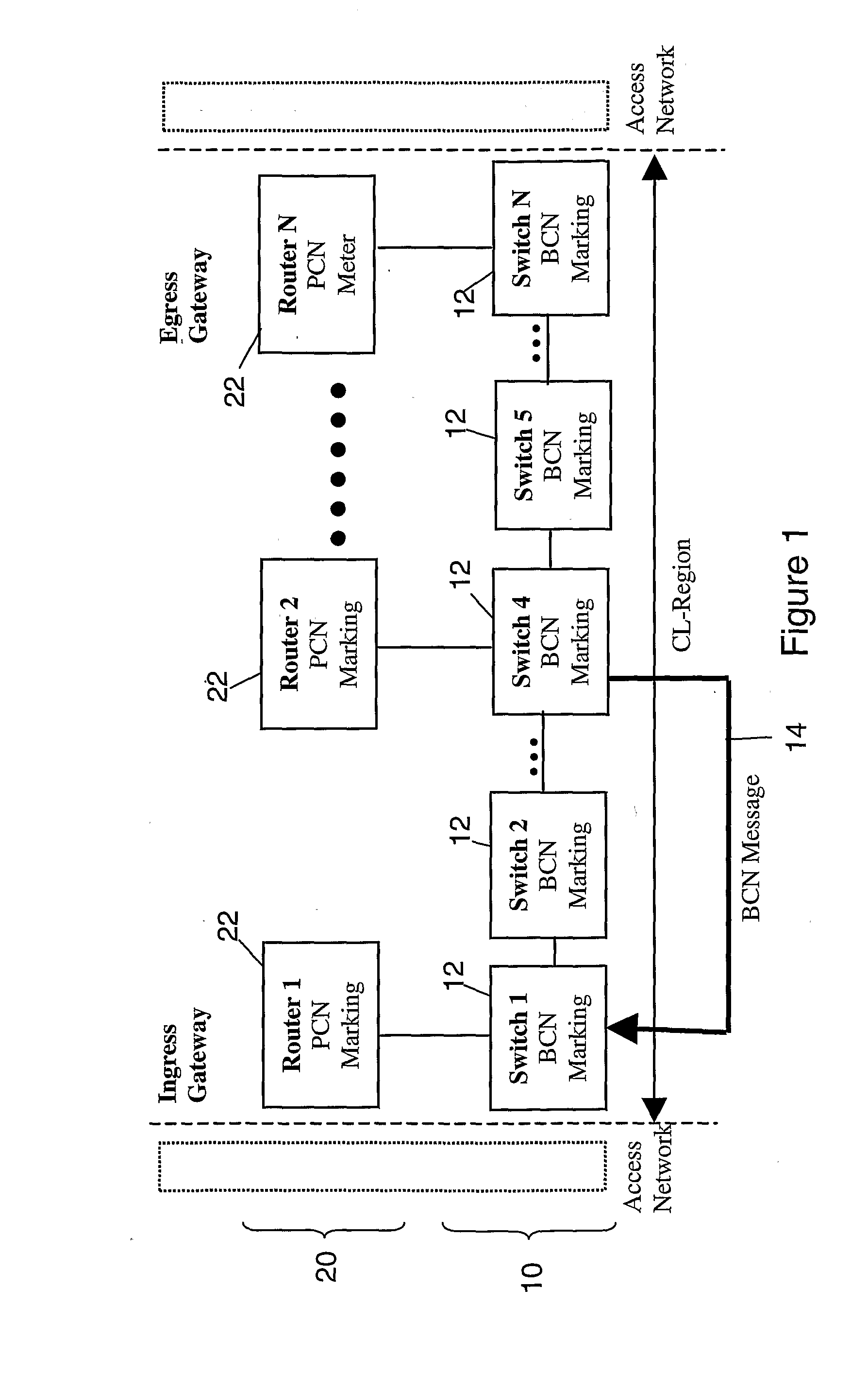
[0063]As noted previously, FIG. 1 illustrates typical network elements, in terms of a plurality of routers 22 provided in the network layer 20, and a plurality of switches 12 forming the links between routers 22, in the data link layer 10. Packets from higher layers access the core network via an access network, and are fed to the ingress gateway shown as router 1 in the controlled load region of the network. Router 1 determines the routing for the received packets, and passes the packets to its associated data link layer switch, in this case switch 1, for transmission to the next hop router in the network layer. The next hop between router 1 and router 2 in the network layer may comprise several individual data links, formed from switches 1 to 4 in the data link layer 10. Typically, the data link layer may comprise an Ethernet, or the like.

[0064]At the data link layer the network layer pac...


PUM


Abstract

The present invention provides a method and system wherein congestion information is taken from a lower level in the protocol stack and used for congestion marking in a higher layer. In particular, the method and system of the invention from a first aspect provide for congestion information in the lower layer to be generated downstream at a congested node, and to be fed back upstream to a source node. The source node then passes the congestion information, or information derived therefrom, up to the corresponding network element responsible for higher layer functions in the protocol stack, where higher level congestion marking can then be performed in dependence on the received lower level congestion information. Thus, congestion information from the lower layer which can typically be generated earlier before significant congestion occurs can be used in higher layer congestion control functions. Preferably the lower layer is the data link layer, and the higher layer is the network layer.

Description

TECHNICAL FIELD[0001]The present invention relates to packet switched data networks, and in particular to a method and system for congestion marking data packets in a higher layer in the protocol stack, based upon congestion information obtained from a lower layer in the stack.BACKGROUND TO THE INVENTION[0002]“Congestion Marking” in data networks is the practice of setting a certain value in a particular field in a packet header to indicate that the packet has experienced congestion at a hop in a network as the packet traverses the network as part of a flow. If the packet continues to experience congestion at a later hop, then the router at the later hop can decide to drop the congestion marked packet, to alleviate congestion within the network as a whole. Congestion marking in Internet Protocol (IP) networks is well known, and typically operates by the network layer router “marking” a packet (in the IP header) when traffic is above a certain threshold. In particularly, IETF RFC 316...

Claims


Application Information

Patent Timeline
Patent Type & Authority Applications(United States)
IPC IPC(8): H04L12/26H04L47/2491H04L47/30H04L47/31
CPCH04L47/10H04L47/11H04L47/12H04L47/245H04L69/32H04L47/26H04L47/30H04L47/31H04L47/33H04L47/2491H04L69/325H04L69/324
Inventor TAY, HUI MIN J.CORLIANO, GABRIELEEARDLEY, PHILIP L.BRISCOE, ROBERT J.
Owner BRITISH TELECOMM PLC
Why Eureka
Try Eureka