
Method and apparatus for blind source separation

a technology for separating methods and sources, applied in the field of methods and equipment for separating blind sources, can solve problems such as difficulty in combining results across frequencies

Inactive Publication Date: 2009-10-29
UNIV COLLEGE DUBLIN NAT UNIV OF IRELAND DUBLIN
View PDF0 Cites 17 Cited by
  • Summary
  • Abstract
  • Description
  • Claims
  • Application Information

AI Technical Summary

Benefits of technology

The present invention provides a method for blind source separation of M mixtures of N signal sources, even when N>M. The method involves decomposing the mixtures into sparse representations, identifying peaks in the histogram, and assigning m instantaneous demixtures to the output representations. The method can be implemented in either a batch or iterative version and can be used in various applications such as speech recognition, audio source separation, and radar detection. The invention provides a more accurate and reliable way to identify and separate sources in complex mixtures.

Problems solved by technology

However, at each frequency the N signal subspace vectors are permutated and so, without knowledge of this random permutation, combining results across frequencies becomes difficult as disclosed by H. Sawada, R. Mukai, S. Araki, and S. Makino, “A robust and precise method for solving the permutation problem of frequency-domain blind source separation,” IEEE Trans.

Method used


Image

  • Method and apparatus for blind source separation
  • Method and apparatus for blind source separation
  • Method and apparatus for blind source separation

Examples


first embodiment

[0051]In the first embodiment, where the invention operates under a strong WDO assumption Λ is a 1-by-1 scalar λ, Σ has all near zero entries and

 [Ex(ω,τ)Ey(ω,τ)]

is a 2 m-by-1 vector so as a result the scalar φ is given by

φ=EX(ω,τ)†EX(ω,τ)†

[0052]Furthermore when the expectation operator of equation (10) is approximated by an instantaneous estimate, i.e.

Rzz(ω,τ)=[XW(ω,τ)YW(ω,τ)][XW(ω,τ)HYW(ω,τ)H]

the expression (11) is equivalent to

φ=XW(ω,τ)†YW(ω,τ)

and so in this case the subspace decomposition of the spatial covariance matrix is unnecessary. In the M=2 case this implementation reduces to conventional DUET. Thus, the present invention applies to multichannel (M>2) implementations of this embodiment.

[0053]The steps involved in the multichannel implementation of the first embodiment are as follows:

Step 1

[0054]A uniformly spaced linear array of M sensors receives M anechoic mixtures x1(t), x2(t), . . . , xM(t), of N WDO source signals. These M signals are represented in the 2(M−1)-by-1 t...

second embodiment

[0060]the invention is based on a weak-WDO assumption that allows for more than one source to have significant energy in the same time-frequency coefficient.

[0061]In this embodiment, ESPRIT direction of arrival (as well as attenuation) estimation is performed at each time-frequency point by considering a group of neighbouring time frames for a given frequency. As in DUET, the estimated mixing parameters are used to create a two-dimensional weighted histogram. The weights for the histogram are obtained from the energy of the time-frequency localized demixtures found by applying a demixing matrix based on the mixing parameters estimates for that time-frequency point.

[0062]From the histogram, N peaks are located corresponding to the N source mixing parameter pairs. Demixing is performed by matrix inversion at each time-frequency point, assigning the resulting demixtures based on the distance to the known source mixing parameters.

[0063]In more detail:

Step 1

[0064]A uniform linear array o...


PUM


Abstract

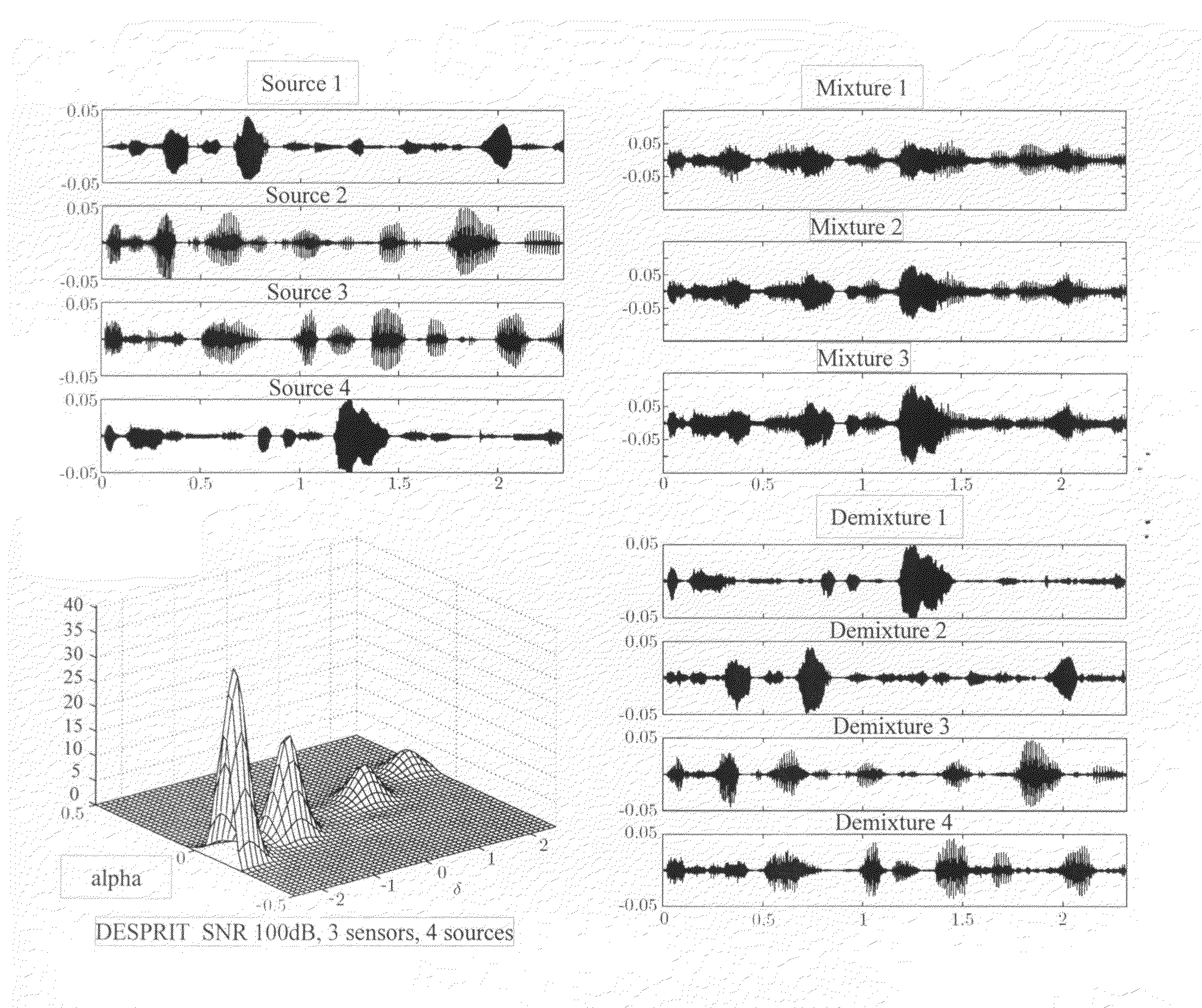
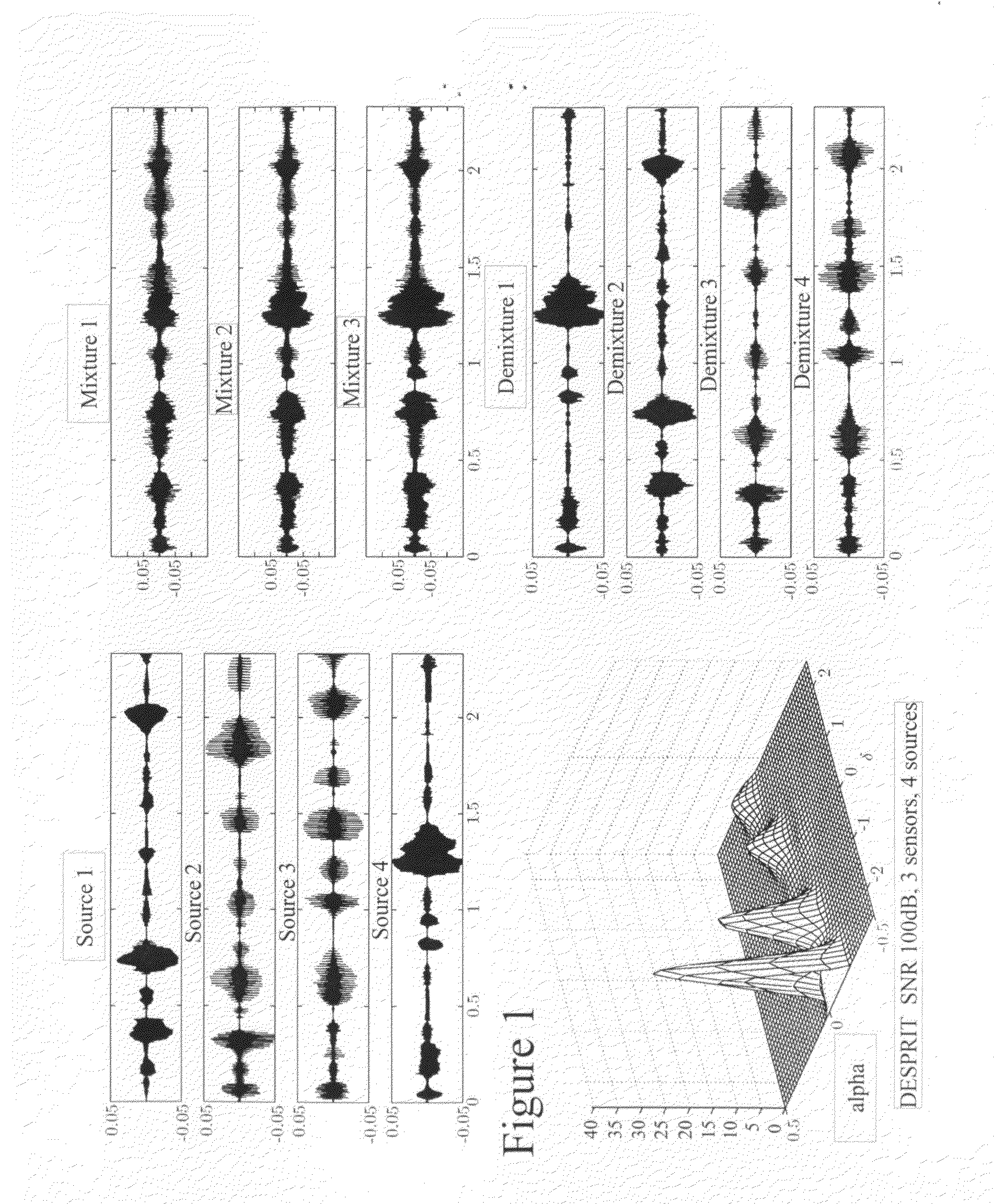
The Direction of Arrival estimation algorithm ESPRIT is capable of estimating the angles of arrival of N narrowband source signals using M>N anechoic sensor mixtures from a uniform linear array (ULA). Using a similar parameter estimation step, the DUET Blind Source Separation algorithm can demix N>2 speech signals using M=2 anechoic mixtures of the signals. The present invention demixes N>M speech signals using M>=2 anechoic mixtures.

Description

FIELD OF THE INVENTION[0001]The present invention provides a method and apparatus for blind source separation (BSS).BACKGROUND OF THE INVENTION[0002]The “cocktail party phenomenon” illustrates the ability of the human auditory system to separate out a single speech source from the cacophony of a crowded room, using only two sensors and with no prior knowledge of the speakers or the channel presented by the room. Efforts to implement a receiver which emulates this sophistication are referred to as Blind Source Separation techniques, examples of which are described by A. J. Bell and T. J. Sejnowski, “An information maximization approach to blind separation and blind deconvolution,” Neural Computation, vol. 6, pp. 1129-1159, 1995. no. 5, pp. 530-538, September 2004; P. Comon, “Independent component analysis: A new concept?” Signal Processing, vol. vol. 36, no. 8, pp. 287-314, 1994; and A. Hyvarinen, J. Karhunen, and E. Oja, “Independent component analysis,” Wiley Series on Adaptive and...

Claims


Application Information

Patent Timeline
Patent Type & Authority Applications(United States)
IPC IPC(8): G06K9/00G10L11/00G10L21/02G10L21/028
CPCG10L21/028G06K9/624G06F18/2134
Inventor FEARON, CONORRICKARD, SCOTTMELIA, THOMAS
Owner UNIV COLLEGE DUBLIN NAT UNIV OF IRELAND DUBLIN
Learn More