Method and apparatus for detecting passive optical network failures, and passive optical network system thereof

a passive optical network and detection method technology, applied in the field of communication technology, can solve problems such as optical distribution network failures, laser transceivers failures, line terminal failures, etc., and achieve the effect of reducing manual analysis and reducing the cost of pon systems

Active Publication Date: 2009-10-29
HUAWEI TECH CO LTD
View PDF7 Cites 59 Cited by
  • Summary
  • Abstract
  • Description
  • Claims
  • Application Information

AI Technical Summary

Benefits of technology

[0018]According to the embodiments of the present invention, by monitoring the monitoring parameters of the OLT and the ONU respectively, the monitoring information of the peer device can be obtained, for example, the OLT obtains the monitoring information of the ONU, before a failure triggers communication interruption. Therefore, the PON system failure can be predic...

Problems solved by technology

The fiber network failures of the PON system include: Optical Distribution Network (ODN) failures, laser transceiver failures, Optical Line Terminal (OLT) failures, and Optical Network Unit (ONU) failures.
The ODN failures include: fiber break, connection failure, and increasing attenuation caused by bend.
Connection failures include: connector loos...

Method used


Image

  • Method and apparatus for detecting passive optical network failures, and passive optical network system thereof
  • Method and apparatus for detecting passive optical network failures, and passive optical network system thereof
  • Method and apparatus for detecting passive optical network failures, and passive optical network system thereof

Examples


embodiment 1

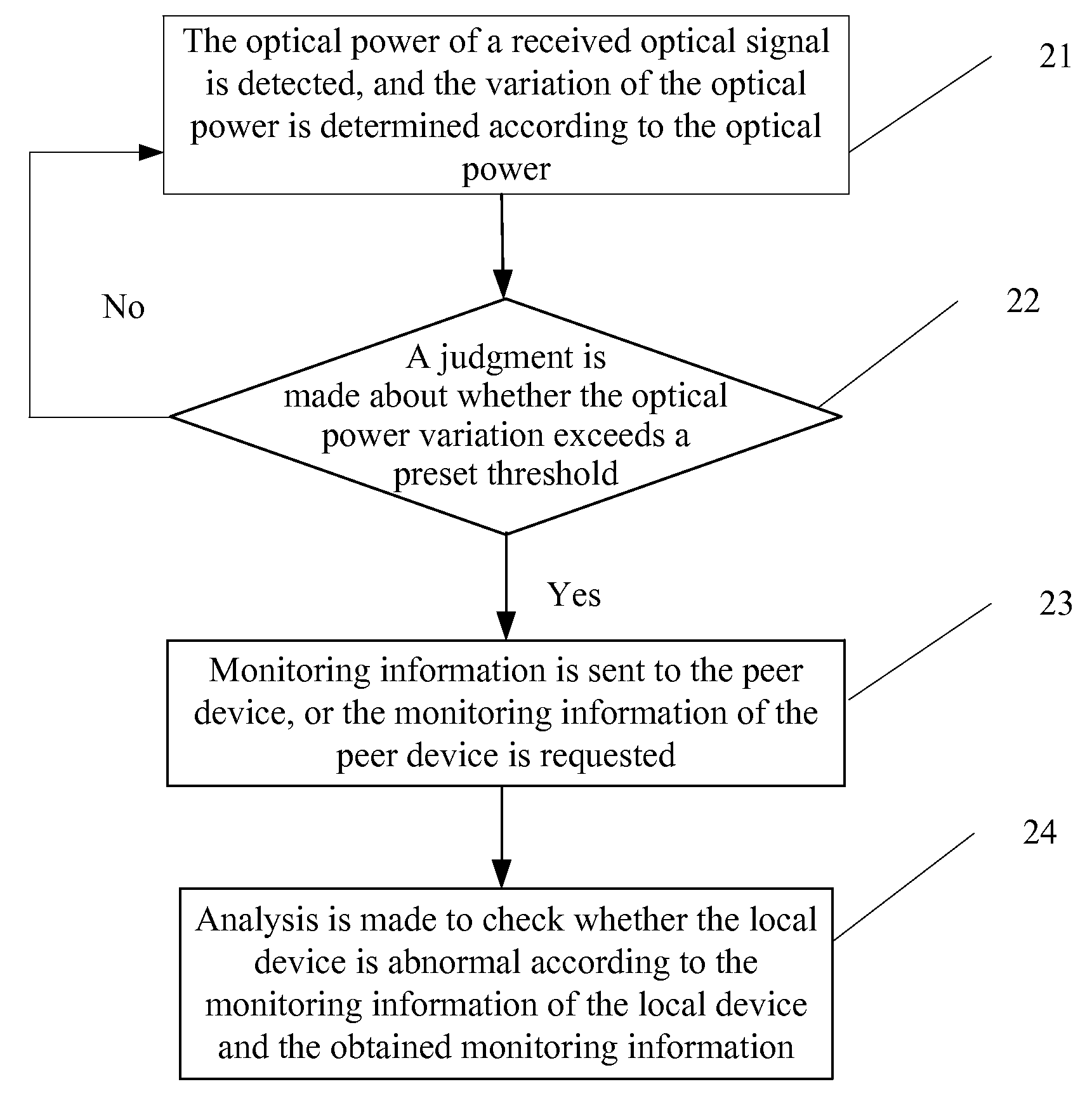
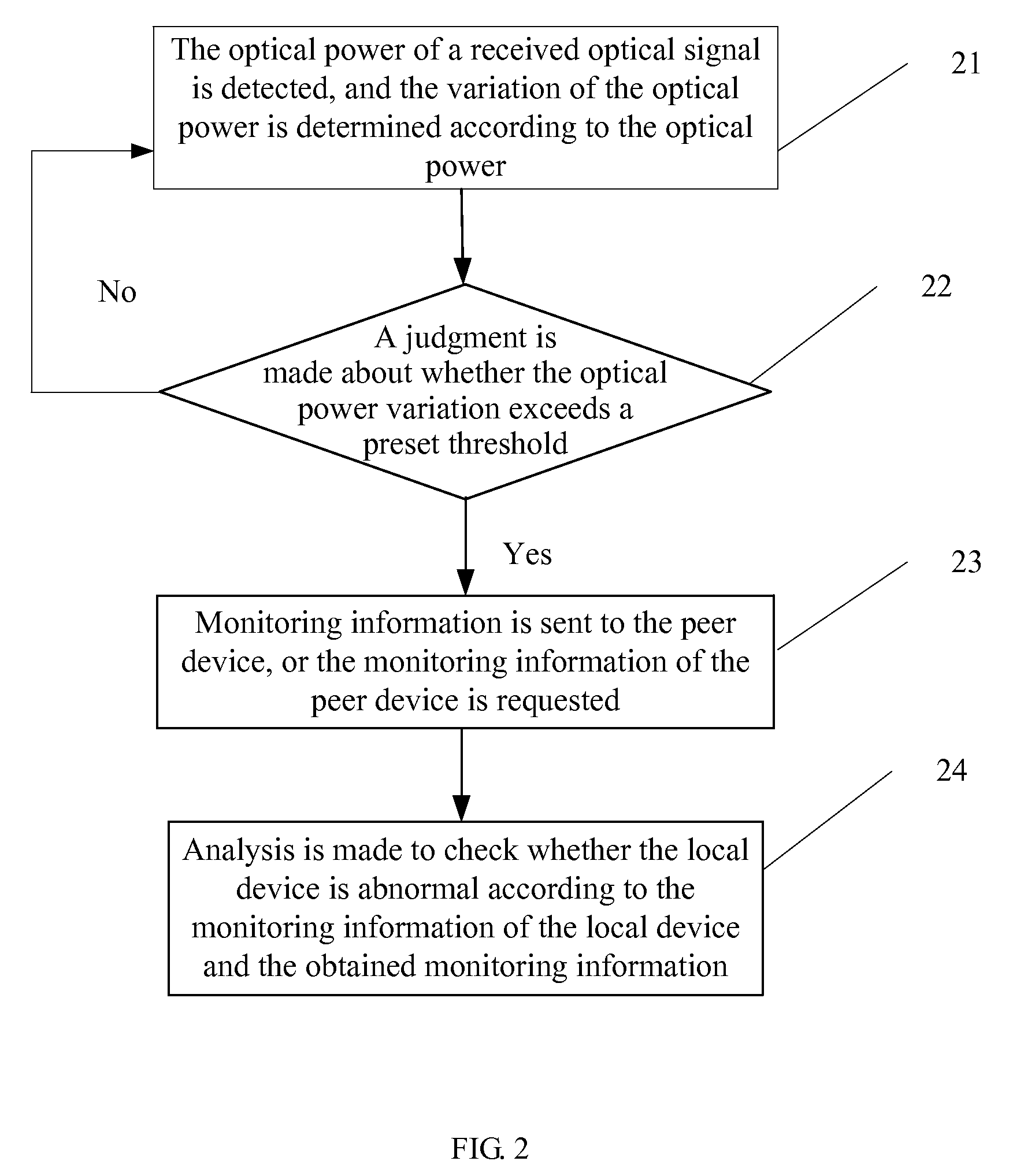
[0033]When the PON system works normally, the variation of the transmit power of the laser in the ONU and the OLT and the variation of attenuation of the ODN never exceed a specific value. Therefore, the variation of the optical receive power of the transceiver never exceeds a threshold. When the variation of the receive optical power and / or the variation of attenuation exceeds a threshold, a failure is signified. That is, a failure is imminent. In this embodiment, the OLT needs to obtain the monitoring information of the ONU (or the ONU needs to obtain the monitoring information of the OLT). In this way, the OLT (ONU) can perform pre-analysis on the failure causes in view of the monitoring information of the OLT and the ONU, and discover and remove the failure as early as possible. Therefore, in some circumstances, for example, the failure cannot disappear automatically, manual analysis of the failure is avoided, and the OM costs of the PON system are slashed.

[0034]A method for det...

embodiment 1-1

[0054]Through the transmit optical power and the receive optical power monitored in the uplink and downlink directions, the optical attenuation of the uplink and downlink signals may be calculated out. According to the variation of the optical attenuation, a connection failure or bend is determined. When the optical attenuation increases, if the variation of the optical attenuation of the downlink signal is far greater than that of the uplink signal, for example, over 0.5 dB higher, the failure is determined as a bend; if the difference between them is small, for example, less than 0.1 dB, the failure is determined as a connection failure.

embodiment 1-2

[0055]If the transmit optical power decreases but the bias current and / or drive current of the laser remains unchanged, it is determined that the laser fails. If the drive current and / or bias current of the laser increases but the transmit optical power does not change obviously, it is determined that the laser has aged.


PUM


Abstract

A method and apparatus for detecting Passive Optical Network (PON) failures, and a PON system are provided to obtain the monitoring information of a peer device before a PON system failure occurs. The method includes: obtaining monitoring information of an Optical Line Terminal (OLT) and an Optical Network Unit (ONU); and determining a failure of a passive ONU according to the obtained monitoring information of the OLT and the ONU. The monitoring information of the peer device is obtained before a PON system failure occurs. Thus the failure is discovered in time, quick troubleshooting is ensured, and the costs of system maintenance are reduced.

Description

CROSS-REFERENCE TO RELATED APPLICATIONS[0001]This application is a continuation of International Patent Application No. PCT / CN2008 / 070818, filed on Apr. 26, 2008, which claims priority to Chinese Patent Application No. 200710098058.4, filed on Apr. 26, 2007, both of which are hereby incorporated by reference in their entireties.FIELD OF THE INVENTION[0002]The present invention relates to a communication technology, and in particular, to a method and apparatus for detecting Passive Optical Network (PON) failures, and a PON system.BACKGROUND OF THE INVENTION[0003]Optical access networks are booming currently. Compared with a point-to-point optical access network, a point-to-multipoint optical access network, that is, PON, slashes the network construction costs because a PON central office may divide one fiber into scores of fiber channels or even more channels connected to users. Currently, the representative PON technologies are Gigabit Passive Optical Network (GPON) and Ethernet Pas...

Claims


Application Information

Patent Timeline
IPC IPC(8): H04B10/08H04B10/079
CPCH04B10/0791H04L41/0677H04L43/0847H04Q2011/0083H04Q11/0067H04Q2011/0081H04L43/16
Inventor YANG, SULIN
Owner HUAWEI TECH CO LTD
Why Eureka
Try Eureka