
Nitride based semiconductor device using nanorods and process for preparing the same

a technology of nanorods and semiconductor devices, which is applied in the direction of semiconductor devices, basic electric elements, electrical equipment, etc., can solve the problems of significant deterioration of the performance of the device manufactured using, unsuitable mass production, and difficulty in large-diameter substrate production, so as to reduce thermal stress

Active Publication Date: 2009-10-29
SAMSUNG ELECTRONICS CO LTD
View PDF5 Cites 10 Cited by
  • Summary
  • Abstract
  • Description
  • Claims
  • Application Information

AI Technical Summary

Benefits of technology

[0013]It is another object of the present invention to provide a process for preparing a nitride based semiconductor device which is capable of effectively inhibiting crack generation when forming the GaN layer on the silicon substrate.
[0017]The amorphous matrix layer is preferably made up of silicon silicone oxides or silicon silicone nitrides. Use of the nitride based semiconductor device including a composite layer of a nanorod-amorphous matrix layer makes it possible to manufacture semiconductor optical devices such as LEDs having a crack-free high-quality GaN layer.
[0020]Further, the process may further comprise a step of separating the silicone substrate, nanorods and matrix layer from the GaN layer. Therefore, a thin film including the GaN layer may be obtained. In this case, the separation step may be easily performed by wet etching. By removing the silicon substrate from the GaN layer via the separation step as mentioned above, the problem can be obviated in which the silicon substrate absorbs light. In other words, when employing the GaN layer formed in accordance with the present invention in the LED, the silicone substrate can be easily removed such that light generated from an active layer is not absorbed by the silicon substrate.
[0021]Further, the process may further comprise a step of separating the silicone substrate, nanorods and matrix layer from the GaN layer. Therefore, a thin film including the GaN layer may be obtained. In this case, the separation step may be easily performed by wet etching. By removing the silicone substrate from the GaN layer via the separation step as mentioned above, the problem can be obviated in which the silicone substrate absorbs light. In other words, when employing the GaN layer formed in accordance with the present invention in the LED, the silicone substrate can be easily removed such that light generated from an active layer is not absorbed by the silicone substrate.
[0023]In accordance with the present invention, intercalating a plurality of nanorods aligned in the vertical direction on the Si substrate and an amorphous matrix layer between a lower Si substrate and upper GaN layer may effectively alleviate thermal stress due to differences in the thermal expansion coefficient between the Si substrate and GaN layer. That is, even when the GaN layer is grown at a high temperature using partially protruded nanorods over the matrix layer as the seed, the GaN layer is minimally affected by thermal stress due to differences in the thermal expansion coefficient between the Si substrate and GaN layer, upon cooling the GaN layer. This is because the nanorods and amorphous matrix layer serve as a sponge to absorb stress between the Si substrate and GaN layer. Therefore, there is substantially no cracking on the upper GaN layer.

Problems solved by technology

However, such substrates are expensive and the size of the substrate is limited to a range of about 2 to 3 inches, resulting in difficulty of large diameter substrate production and thus being unsuitable for mass production.
Such cracks formed on the GaN layer lead to significant deterioration of performance of devices manufactured using the GaN layer and have fatal effects on the service life of such devices.
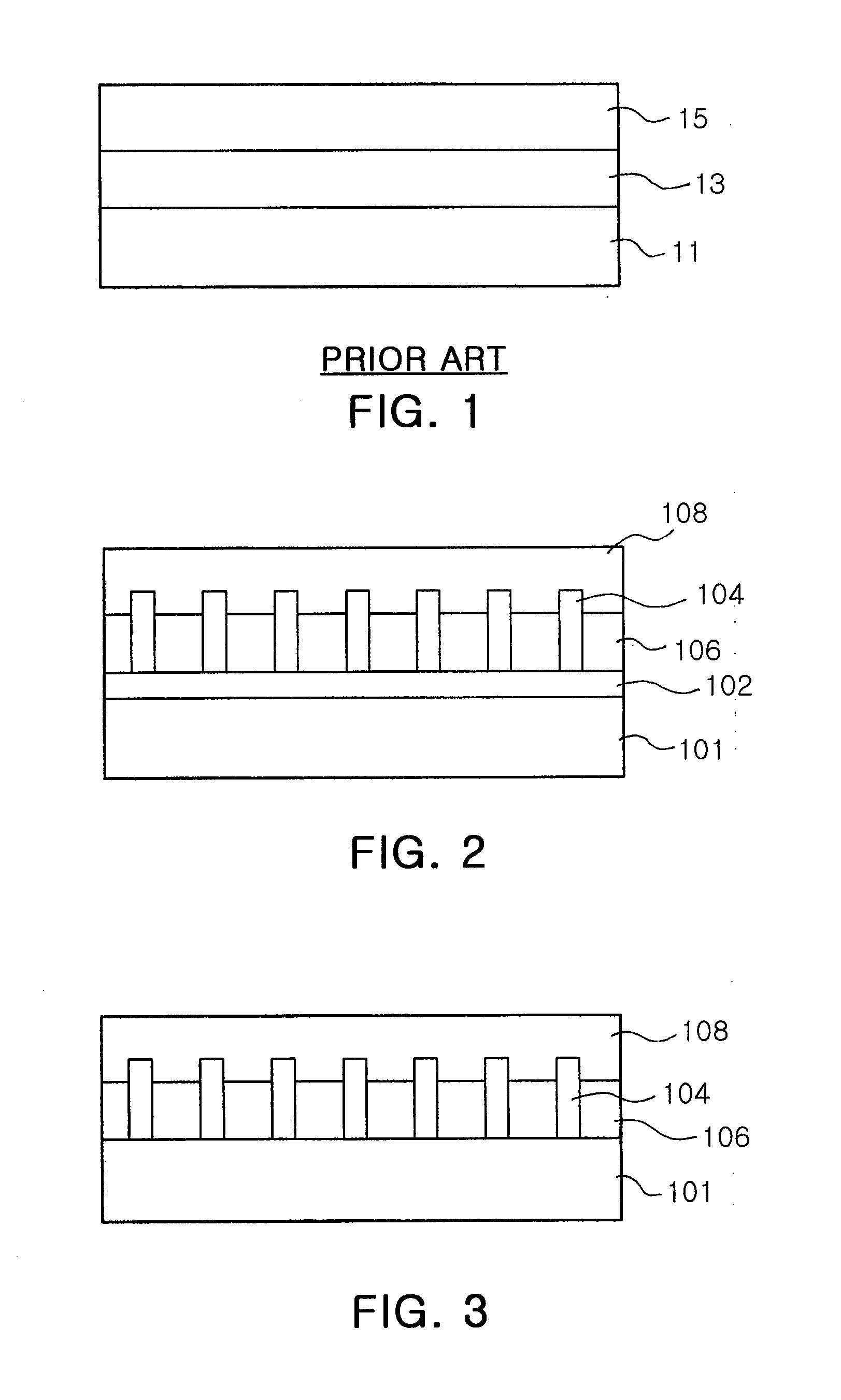
However, formation of the AlxGa1-xN buffer layer 13 fails to effectively alleviate tensile stress due thermal expansion coefficient differences between the Si substrate 11 and GaN layer 15, thus causing production of a crack network on the surface of the grown GaN layer 15.
Such a crack network not only degrades the performance of optical devices such as LEDs prepared on the basis of the GaN layer 15 but also drastically reduces the service life of the devices.
However, this method also fails to solve fundamental problems such as cracking.

Method used


Image

  • Nitride based semiconductor device using nanorods and process for preparing the same
  • Nitride based semiconductor device using nanorods and process for preparing the same
  • Nitride based semiconductor device using nanorods and process for preparing the same

Examples


Embodiment Construction

[0030]The present invention now will be described more fully with reference to the accompanying drawings, in which embodiments of the invention are shown. The present invention may, however, be embodied in many different forms and should not be construed as being limited to the embodiments set forth herein; rather, these embodiments are provided so that this disclosure will be thorough and complete, and will fully convey the concept of the invention to those skilled in the art. Therefore, in the drawings, shape and size of some elements may be exaggerated for clarity, and like numbers refer to like elements throughout.

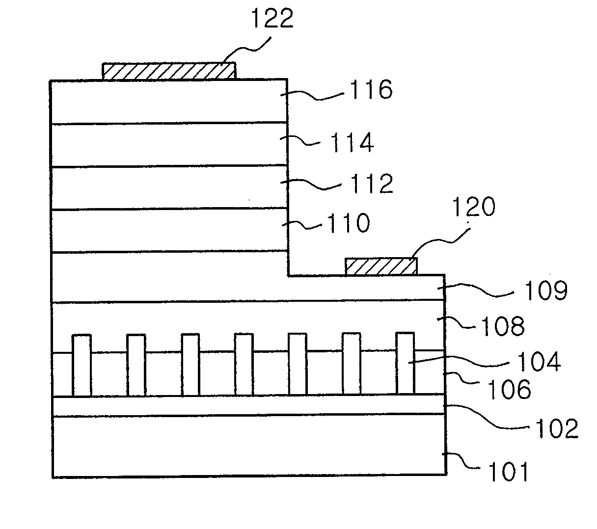
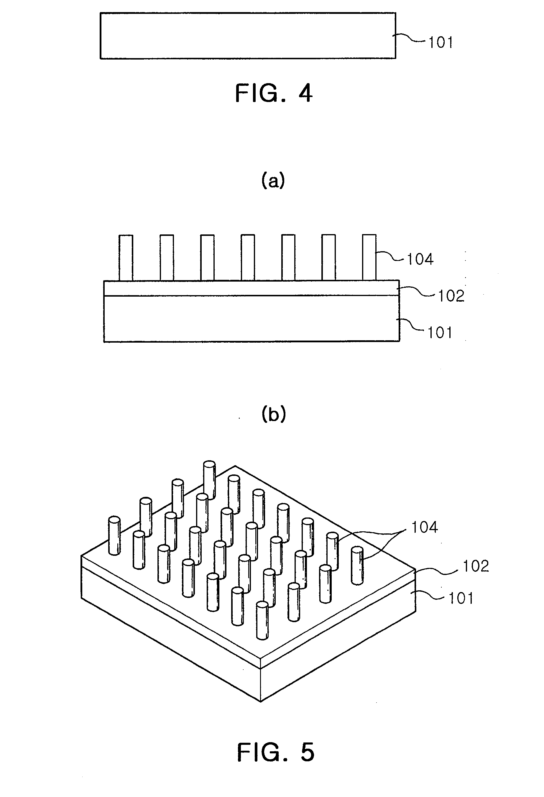
[0031]FIG. 2 is a view schematically showing a cross-sectional structure of a nitride based semiconductor device in accordance with one embodiment of the present invention. Referring to FIG. 2, a ZnO buffer layer 102, obtained by low-temperature growth, was formed on a Si substrate 101. A plurality of nanorods 104 made of ZnO was aligned on the ZnO buffer layer 102 in ...


PUM

PropertyMeasurementUnit
temperatureaaaaaaaaaa
pressureaaaaaaaaaa
temperatureaaaaaaaaaa

Abstract

Disclosed are a nitride based semiconductor device, including a high-quality GaN layer formed on a silicone substrate, and a process for preparing the same. A nitride based semiconductor device in accordance with the present invention comprises a plurality of nanorods aligned and formed on the silicone substrate in the vertical direction; an amorphous matrix layer filling spaces between nanorods so as to protrude some upper portion of the nanorods; and a GaN layer formed on the matrix layer.

Description

RELATED APPLICATION[0001]This application is a Divisional application of U.S. patent application Ser. No. 11 / 204,226, filed on Aug. 16, 2005, claiming priority of Korean Patent Application No. 10-2004-0087202, filed on Oct. 29, 2004, the entire contents of each of which are hereby incorporated by reference.BACKGROUND OF THE INVENTION[0002]1. Field of the Invention[0003]The present invention relates to a nitride based semiconductor device and a process for preparing the same, and more particularly to a nitride based semiconductor device which has nanorods and an amorphous matrix layer on a substrate and thus is capable of inhibiting occurrence of cracks and a process for preparing the same.[0004]2. Description of the Related Art[0005]Generally, light emitting diodes (LEDs) are broadly divided into blue and green visible light, and UV light LEDs, using a nitride based semiconductor, and green and red LEDs using semiconductor materials such as GaAs or GaP. Recently, owing to developmen...

Claims


Application Information

Patent Timeline
Patent Type & Authority Applications(United States)
IPC IPC(8): H01L21/20H01L33/12H01L33/16H01L33/32H01L33/34
CPCH01L21/02381H01L21/02458H01L21/02472H01L21/02502H01L21/02513H01L21/0254H01L21/0262H01L21/02639H01L21/02647H01L33/007
Inventor KIM, MIN HOKOIKE, MASAYOSHIMIN, KYEONG IKLEE, SEONG SUKJANG, SUNG HWAN
Owner SAMSUNG ELECTRONICS CO LTD
Learn More