Therapeutic Light System

Inactive Publication Date: 2009-10-29
SPIVAK PAUL
View PDF10 Cites 10 Cited by
  • Summary
  • Abstract
  • Description
  • Claims
  • Application Information

AI Technical Summary

Benefits of technology

[0020]An advantage of the present invention is that is that a biologically effective dose of an effective irrradiance of a therapeutic light source can be achieved.
[0021]Another advantage of the present invention is

Problems solved by technology

However, in order to elicit a therapeutic effect, a patient's exposure to any selected wavelength of light is accompanied by one main side-effect: increased thermal retention.
The exposure of a patient's skin to the use of LEDs, fluorescent lamps, dichromic lamps or very bright, full-spectrum light over a period of time results in thermal:effects which themselves can be de

Method used


Image

  • Therapeutic Light System
  • Therapeutic Light System
  • Therapeutic Light System

Examples


Embodiment Construction

[0026]The best mode for carrying out the invention is presented in terms of its preferred embodiment, herein depicted within the Figures

1. Detailed Description of the Figures

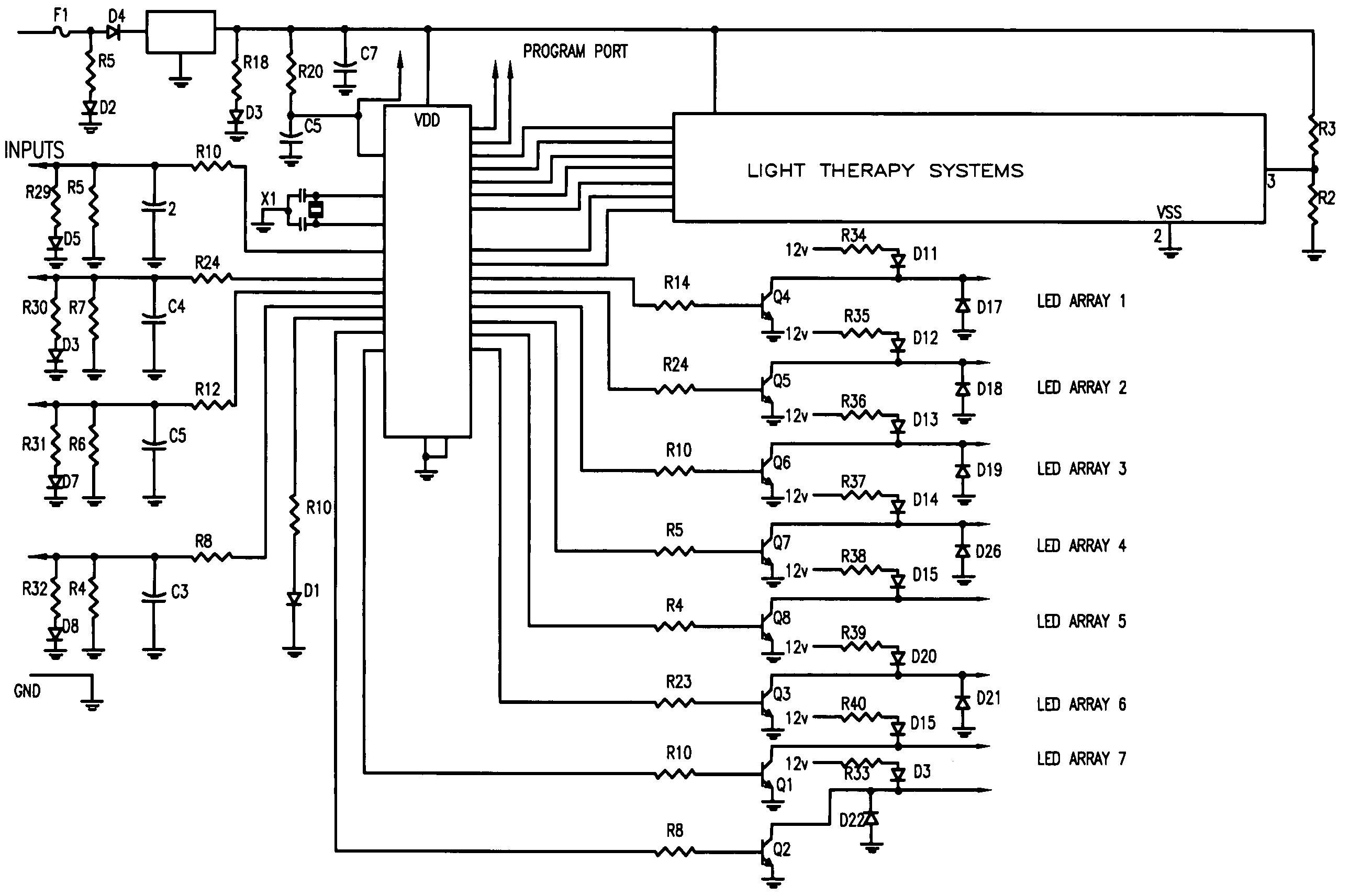
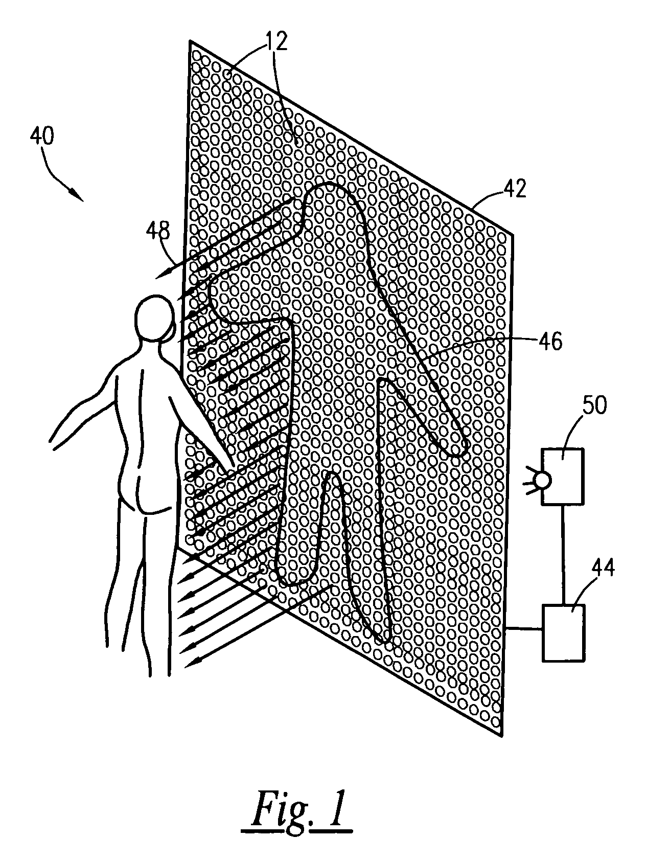
[0027]The present invention provides for an array of light emitting diodes (LED) as exemplified in FIG. 1. As is well-known in the art, LED's have generally small and round physical characteristics. Accordingly, a plurality of LED's can be arranged into matrixes of virtually any type of shape. A plurality of LED's 12 is arranged into a matrix 14. When energized by a power and control system 18 the matrix 14 projects a light illumination pattern 16. It is preferred that the matrix 14 shape conform to the intended target of the UV illumination pattern 16, a user P. In this fashion the present embodiment provides superior efficiencies compared to prior art fluorescent tube tanning systems, which necessarily consist of generally rectilinear arrays of long linear fluorescent tubes.

[0028]The array of LED's may be in c...


PUM


Abstract

A non-thermal low dose light emitting diode (LED) array provides for the application of therapeutically specific radiation is provided. The array delivers radiation to the intended target surface at a controlled intensity. The intensity is controlled with a specific sequence of pulsing by pulse driving a matrix-arrayed LED. The modulation of the therapeutically specific radiation is at a frequency outside the user's visually perceptive range, but with a visually perceptible cycle. The cycle is initiated by a strobe rate very slow and perceptible to the user and then ramp up rapidly to over 30 cycles per second for the dosage period. The cycle is terminated by ramping down the strobe rate from above 30 cycles per second to a slower, visually perceptible level at the end of the dosage period. The instant abstract is neither intended to define the invention disclosed in this specification nor intended to limit the scope of the invention in any way.

Description

RELATED APPLICATIONS[0001]The present invention claims priority benefit from the following, previously filed applications:[0002]U.S. Pat. No. 6,828,576, issued on Dec. 7, 2004, claiming benefit of Provisional Application No. 60 / 477,685, filed on Jun. 11, 2003;[0003]U.S. Ser. No. 10 / 977,531 filed on Oct. 29, 2004 and claiming benefit of Provisional Application No. 60 / 477,685, filed on Jun. 11, 2003; and[0004]U.S. Ser. No. 10 / 633,920, filed on Avg. 4, 2003 and claiming benefit of Provisional Application No. 60 / 477,685, filed on Jun. 11, 2003.[0005]The entire disclosure and contents of the above applications are hereby incorporated by reference as if fully rewritten.BACKGROUND OF THE INVENTION[0006]1. Field of the Invention[0007]This invention relates to a therapeutic light systems and, more specifically, to an improvement method of operating such systems to allow for improved effectiveness without the known detrimental side effects.[0008]2. Description of the Related Art[0009]Light th...

Claims


Application Information

Patent Timeline
IPC IPC(8): A61N5/06A61N1/00
CPCA61N5/0614A61N2005/0661A61N2005/0652A61N5/0616
Inventor SPIVAK, PAUL
Owner SPIVAK PAUL
Why Eureka
Try Eureka