Network Equipment System

a network equipment and equipment technology, applied in the field of network equipment systems, can solve the problems of requiring a lot of time and effort, affecting the efficiency of network equipment, and difficulty in adding a new network device to the network equipment system constituted by object-oriented language, etc., to achieve the effect of reducing the network load for sharing variables, reducing the number of variables, and restrainting the variable memory exchanger

Inactive Publication Date: 2009-10-29
MATSUSHITA ELECTRIC WORKS LTD
View PDF7 Cites 4 Cited by
  • Summary
  • Abstract
  • Description
  • Claims
  • Application Information

AI Technical Summary

Benefits of technology

[0007]In view of the above problem, the object of the present invention is to provide a network equipment system which is capable of dealing with a system change and system expansion easily and in which there is no fear of occurrence of the deadlock and which can perform optimization of the system.
[0008]In order to solve the above problem, an inventor of the present invention focused attention on a so-called functional language. The functional language is a programming language (for example, Haskell) having a mathematical language specification, and it does not have a concept of a state, and a result thereof is determined by only an argument (arguments), and it has no side-effect and has referential transparency.

Problems solved by technology

When a new network device is added to a network equipment system constituted by the object-oriented language, it is necessary to examine the influence of the new network device upon the whole system, and it requires a lot of time and effort as the system becomes complex.
If the investigation of the system is imperfect, so-called deadlock may occur.
Therefore, as the system becomes complex, it becomes difficult to add a new network device to the network equipment system constituted by the object-oriented language.
Furthermore, because the object has much internal state information, if a problem arises in investigating the system, it is necessary to identify the internal state information and to re-create the state in order to re-create the problem, so, debugging is not easy.
However, in the above network equipment system, because it is difficult to decompose a problem of a whole system into subproblems and there is a dependence relationship between the decomposed subproblems, it is difficult to apply the autonomous distributed system of the above publication.

Method used


Image

  • Network Equipment System
  • Network Equipment System
  • Network Equipment System

Examples


Embodiment Construction

[0025]Hereinafter, the present invention will be described in more detail with reference to the accompanying drawings.

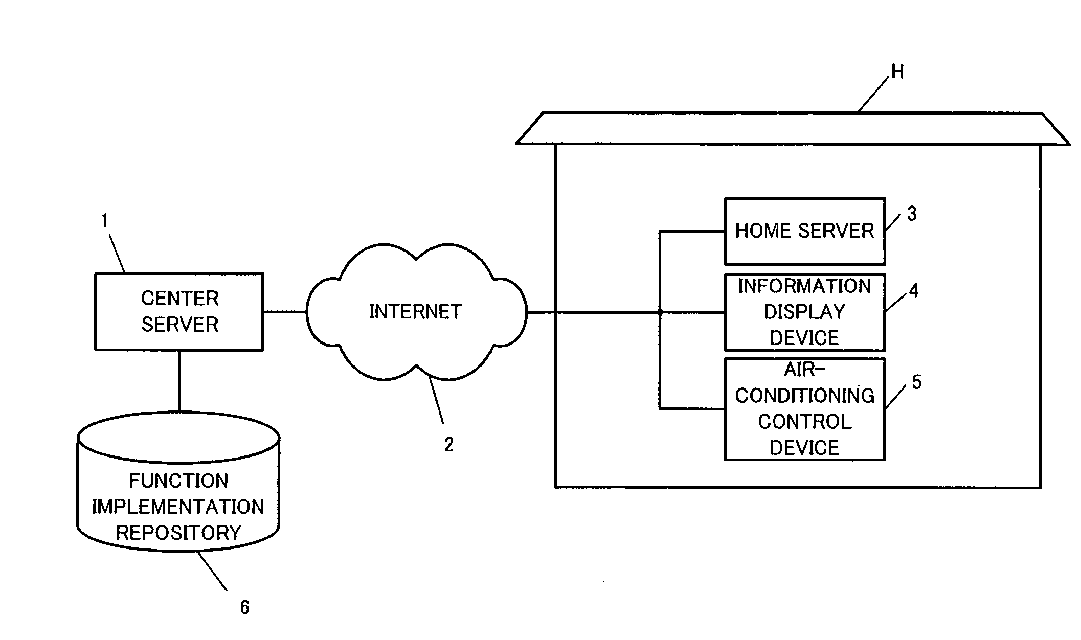
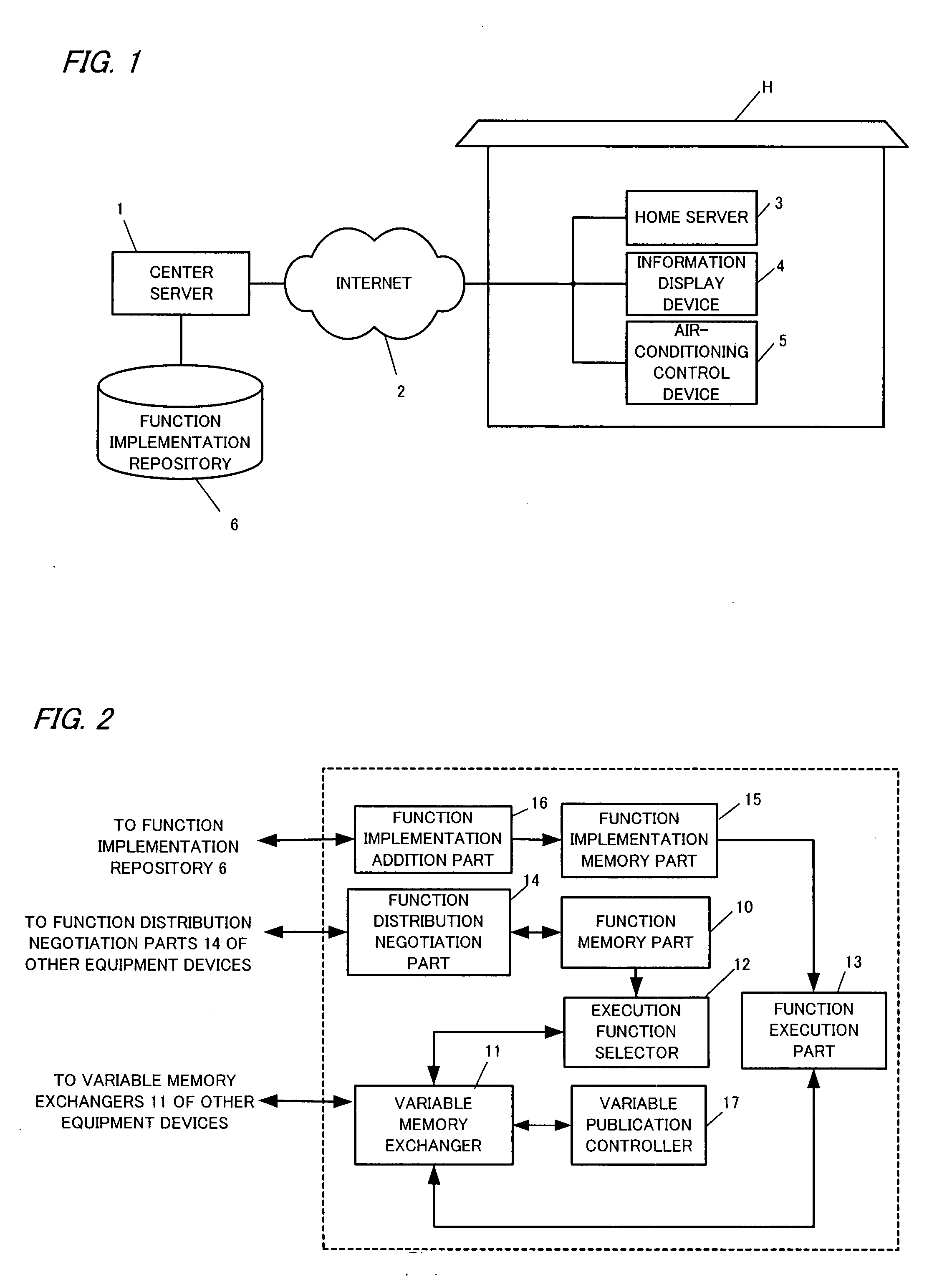
[0026]FIG. 1 is a view showing a configuration of a network equipment system of a distributed functional processing system in accordance with an embodiment of the present invention. In this network equipment system, as network devices, a center server 1, a home server 3 installed in a home H, and various equipment devices, such as an information display device 4 and an air-conditioning control device 5 installed in the home H, are connected to each other through the Internet 2 and a LAN. Although, in order to facilitate understanding, only the above-mentioned network devices are taken as an example in this embodiment, the network devices are not limited to them, of course.

[0027]The center server 1 is configured by a general-purpose computer device with network capability, and it has a function implementation repository 6 for storing implementation of functions which ...


PUM


Abstract

This network equipment system is a system of a functional processing system, and is configured so that each network device performs a function assigned to itself whereby the whole system performs the predetermined action. Each network device has a function memory part 10, a variable memory exchanger 11, an execution function selector 12, and a function execution part 13. The variable memory exchanger 11 is connected to each network device through a telecommunications line, and it stores a variable necessary for execution of the functions stored in the function memory part 10 of each network device, and it shares the variable among the network devices. The execution function selector refers the variable stored in the variable memory exchanger, and it selects an executable function out of the functions stored in the function memory part. The function execution part executes the function selected by the execution function selector and updates the variable stored in the variable memory exchanger by the execution result.

Description

TECHNICAL FIELD[0001]The present invention relates to a network equipment system and, more particularly, to a network equipment system of a distributed functional processing system.BACKGROUND ART[0002]A network equipment system in which a plurality of network devices are connected to each other through telecommunications lines such as the Internet and they perform a predetermined action in concert with each other has been provided. For example, a system in which a home server and various equipment devices in a home (for example, an information display device, an air-conditioning control device, and so on) are connected to each other through the Internet and which controls the equipment devices in the home and / or monitors the power in the home through the Internet has been provided.[0003]Heretofore, in order to design such a system, an object-oriented language is widely used. The object-oriented language has features such as encapsulation, inheritance, polymorphism, and it is effecti...

Claims


Application Information

Patent Timeline
Patent Type & Authority Applications(United States)
IPC IPC(8): G06F15/16
CPCG06F9/465G06F9/5027H04L67/125G06F9/5072G06F9/544G06F9/505
Inventor HATANAKA, TOMOYUKI
Owner MATSUSHITA ELECTRIC WORKS LTD
Why Eureka
Try Eureka