Power management system capable of saving power and optimizing operating efficiency of power supplies for providing power with back-up or redundancy to plural loads

a power management system and power supply technology, applied in the direction of parallel operation of dc sources, instruments, transportation and packaging, etc., can solve the problems of power plant underutilization in daily operation, all electronic components consume some energy to provide functions, and affect operating costs, so as to optimize the operating efficiency of power supplies and save power

Active Publication Date: 2009-10-29
DELTA ELECTRONICS INC
View PDF21 Cites 78 Cited by
  • Summary
  • Abstract
  • Description
  • Claims
  • Application Information

AI Technical Summary

Benefits of technology

[0015]It is an object of the present invention to provide a power management system capable of saving power and optimizing operating efficiency of power supplies for providing power with back-up or redundancy to plural loads, such as servers, computer systems, telecom equipments, etc.

Problems solved by technology

All electronic components consume some energy to provide their functions.
Operating efficiency is a key measure of interest, as this directly impacts operating costs.
Provisioning guidelines for power equipment often utilize worst-case scenarios that can cause the power plant to be underutilized in daily operation.
Operating power supplies at very low output power levels can decrease the efficiency, therefore increasing operating costs.
It is also well known that power supplies are not at its best efficiency when operating at 25% of their rated power.
Many servers naturally are well under-utilizing their power availability.
Operating power supplies at very low output power levels can decrease the efficiency, therefore increasing operating costs.

Method used


Image

  • Power management system capable of saving power and optimizing operating efficiency of power supplies for providing power with back-up or redundancy to plural loads
  • Power management system capable of saving power and optimizing operating efficiency of power supplies for providing power with back-up or redundancy to plural loads
  • Power management system capable of saving power and optimizing operating efficiency of power supplies for providing power with back-up or redundancy to plural loads

Examples


Embodiment Construction

[0056]The present invention will now be described more specifically with reference to the following embodiments. It is to be noted that the following descriptions of preferred embodiments of this invention are presented herein for purpose of illustration and description only. It is not intended to be exhaustive or to be limited to the precise form disclosed.

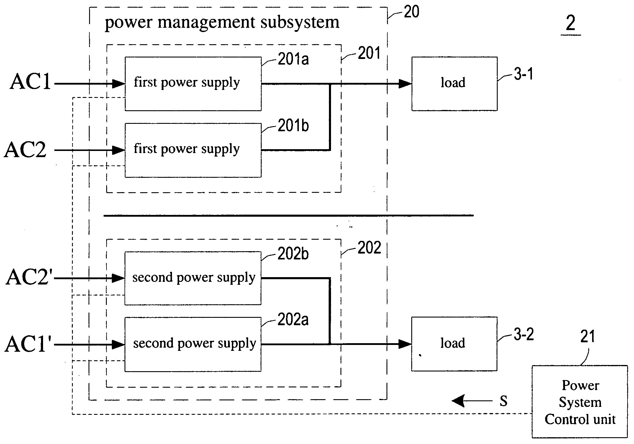
[0057]FIGS. 4A and 4B schematically illustrate a power management system capable of saving power and optimizing operating efficiency of power supplies for providing power with back-up or redundancy to plural loads according to a first preferred embodiment of the present invention. As shown in FIGS. 4A and 4B, the power management system 2 comprises at least one power management subsystem 20 and a plurality of loads, such as device circuits of servers, computer systems or telecom equipments. The power management subsystem 20 comprises a first power module 201, a second power module 202 and a pass-through module 203. The first powe...


PUM


Abstract

The present invention relates to a power management system comprising at least one power management subsystem. Each power management subsystem comprises a first power module coupled to a first load and comprising at least one first power supply for supplying power to the first load; a second power module coupled to a second load and comprising at least one second power supply, wherein at least one second power supply is retractably installed in the second power module and selectively coupled to the second load; and a pass-through module comprising at least one pass-through unit retractably installed in the second power module to replace with the at least one second power supply and selectively connecting the first power module to the second load for allowing the first power module to supply power to the second load.

Description

CROSS-REFERENCE TO RELATED APPLICATIONS[0001]This application claims the benefit of prior U.S. provisional application 61 / 048,294, entitled “Power Management System Capable Of Saving Power And Optimizing Operating Efficiency Of Power Supplies For Providing Power With Back-Up Or Redundancy To Plural Loads” and filed Apr. 28, 2008.FIELD OF THE INVENTION[0002]The present invention relates to a power management system of power supplies for providing power to a plurality of loads, and more particularly to a power management system capable of saving power and optimizing operating efficiency of power supplies for supplying power with back-up or redundancy to a plurality of loads, such as servers, computer systems, telecom equipments, etc.BACKGROUND OF THE INVENTION[0003]All electronic components consume some energy to provide their functions. Operating efficiency is a key measure of interest, as this directly impacts operating costs. For AC to DC power supplies, efficiency is a comparison ...

Claims


Application Information

Patent Timeline
Patent Type & Authority Applications(United States)
IPC IPC(8): G06F1/00
CPCG06F1/263H02J1/14H02J1/102H02J1/001
Inventor CHENG, BRUCE C. H.HUANG, CHI-HSINGJOVANOVIC, MILAN M.
Owner DELTA ELECTRONICS INC
Why Eureka
Try Eureka