
Drilling system with drill string valves

a drilling system and valve body technology, applied in the field of drilling systems, can solve the problems of limited control of the flow of fluid that exits the bit from the surface and the limited use of different means

Active Publication Date: 2009-11-05
SCHLUMBERGER TECH CORP
View PDF22 Cites 63 Cited by
  • Summary
  • Abstract
  • Description
  • Claims
  • Application Information

AI Technical Summary

Benefits of technology

[0005]In another aspect, a method to control borehole fluid flow includes detecting a drilling condition and operating at least one valve in the drill st

Problems solved by technology

The control from the surface of the fluid flow that exits through the bit and different means is very limited.

Method used


Image

  • Drilling system with drill string valves
  • Drilling system with drill string valves
  • Drilling system with drill string valves

Examples


Embodiment Construction

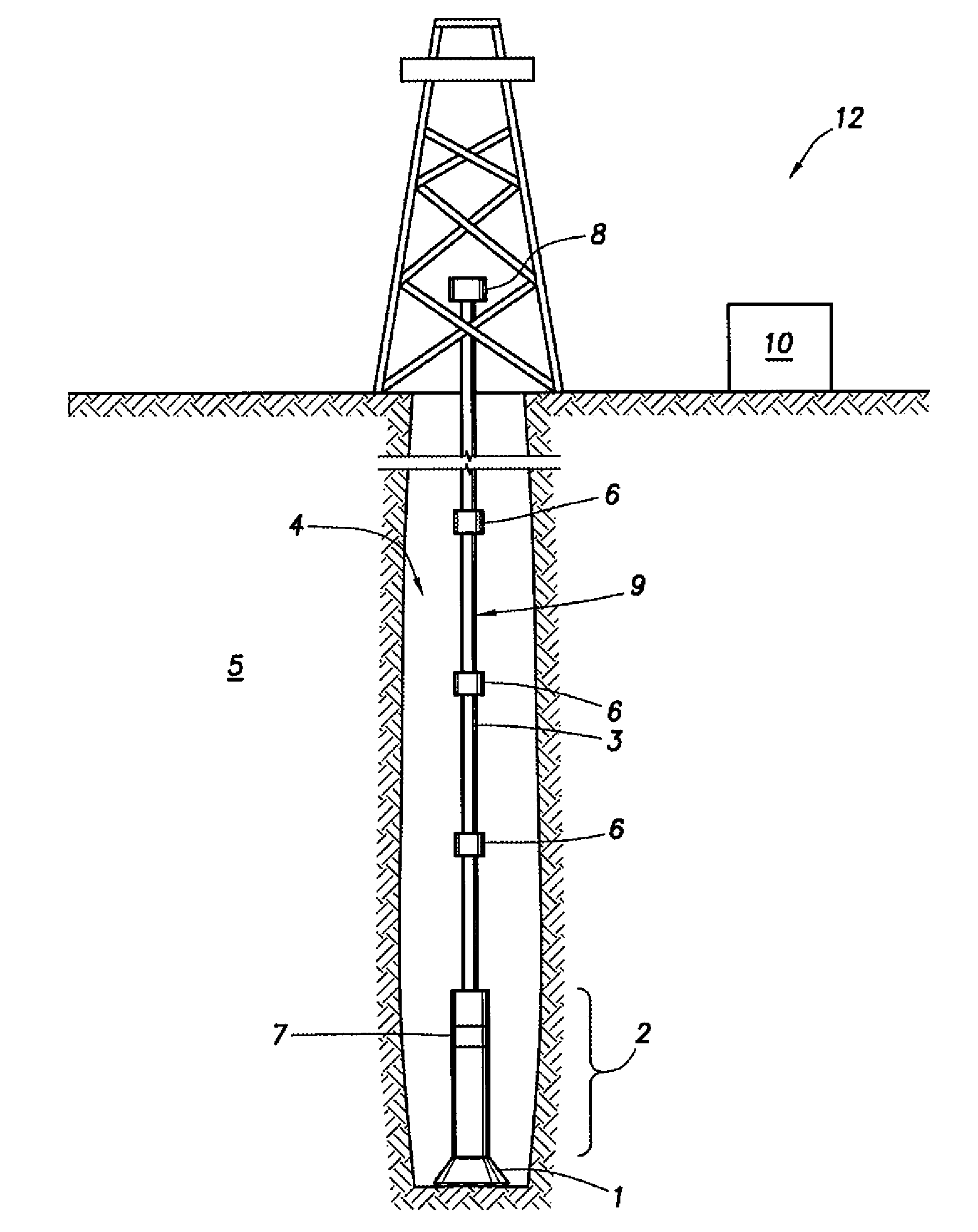
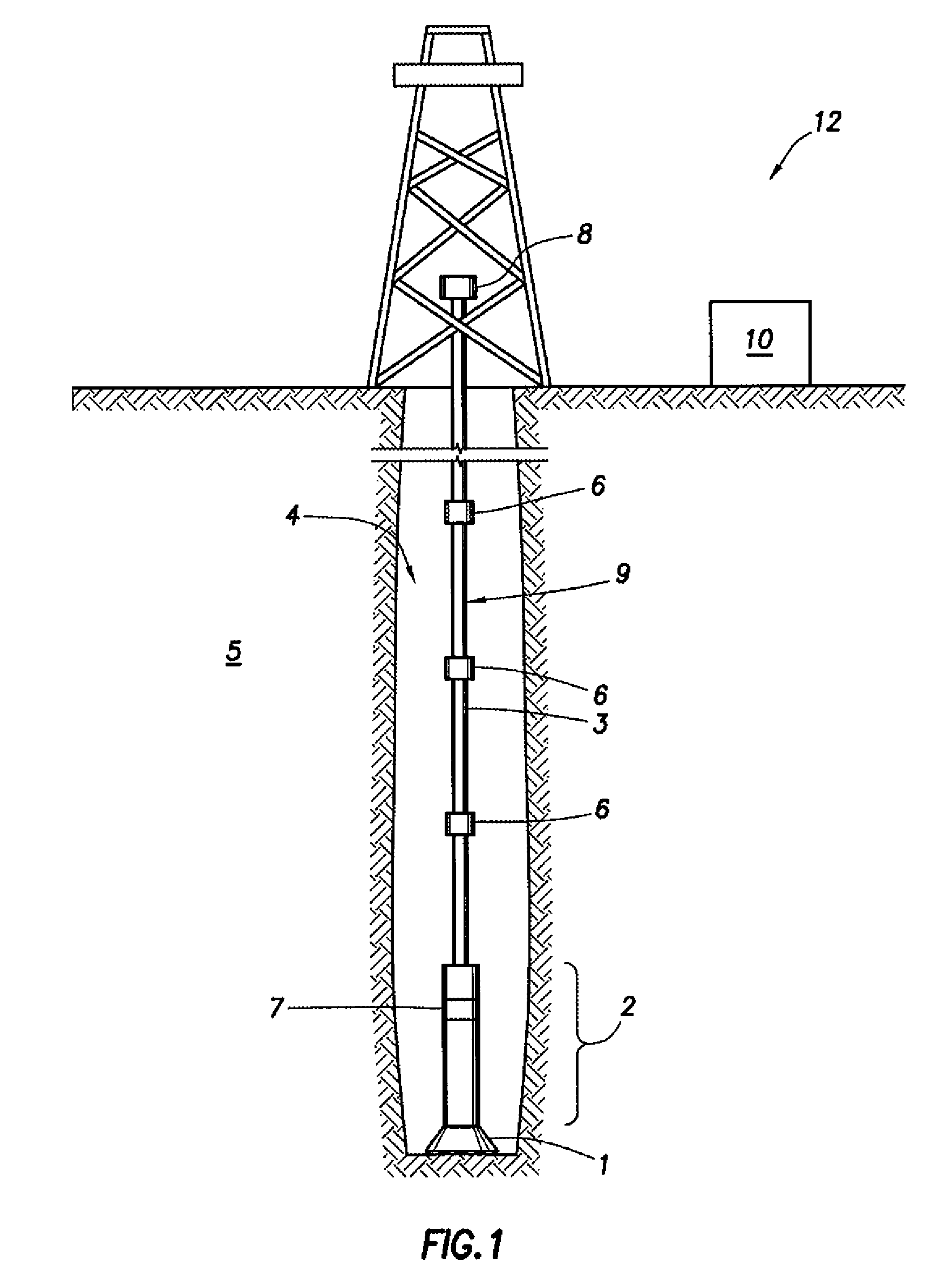
[0033]Hydraulics in conventional drilling requires balancing different requirements. For instance, the fluid flow velocity in the widest section of the annulus must be sufficient to lift cuttings, but the pressure drop in the drillpipe must be within the pump capabilities. Furthermore, the flow velocity in the narrowest part of the annulus should not be so high as to cause erosion or hole widening. Downhole equipment, such as positive displacement motors, turbines and rotary steerable systems also have flow ranges within which they operate. Attempting to reconcile these different requirements may be difficult or even impossible in conventional systems. Allowing some of the flow to exit the drillstem at chosen points, when desired, allows the various requirements to be reconciled much more easily, and adds considerable flexibility to the driller.

[0034]FIG. 1 shows a schematic of an example drilling system 12 that includes a plurality of drill pipe segments 3 that form a drill string ...


PUM


Abstract

A method to control borehole fluid flow includes detecting a drilling condition and operating at least one valve in the drill string to place an exterior of the drill string in fluid communication with an interior of the drill string in response to detecting the drilling condition.

Description

BACKGROUND OF THE INVENTION[0001]A typical drilling system for use in drilling for oil, gas, and other hydrocarbons includes: a drilling rig, a drill string having its upper end mechanically coupled and suspended from the drilling rig, and a bottom hole assembly (“BHA”) mechanically coupled to the lower end of the drill string. The drill string is typically made up of segments of drill pipe that are coupled together, end-to-end, to form a long pipe string. The BHA typically includes a drill bit at its lower end. Wired drill pipe is an emerging technology that may be used to provide communication and power distribution throughout the drilling system. For example, wired drill pipe may be used to transmit data from a measuring device in the BHA to an uphole processor system. In other examples, wired drill pipe may be used to transmit data or instructions from an uphole system to the BHA. In addition, wired drill pipe may provide communications to and from sensors or other electronics p...

Claims


Application Information

Patent Timeline
IPC IPC(8): E21B21/08
CPCE21B21/003E21B34/08E21B21/103E21B21/08
Inventor DOLMAN, LEE F.JEFFRYES, BENJAMIN P.JOHNSON, ASHLEY B.CLARK, BRIANMCCULLAGH, JOHN A.
Owner SCHLUMBERGER TECH CORP
Features
  • Generate Ideas
  • Intellectual Property
  • Life Sciences
  • Materials
  • Tech Scout
  • Unparalleled Data Quality
  • Higher Quality Content
  • 60% Fewer Hallucinations
Learn More