Aircraft flight termination system and method

a technology for aircraft and flight, applied in the direction of gliders, transportation and packaging, weapons, etc., can solve the problems of minor explosion hazards and rapid flight termination, and achieve the effects of safe handling, easy analyzability, and small footprin

Active Publication Date: 2009-11-05
RAYTHEON CO
View PDF9 Cites 11 Cited by
  • Summary
  • Abstract
  • Description
  • Claims
  • Application Information

AI Technical Summary

Benefits of technology

[0007]A flight termination system for an aircraft accomplishes flight termination by shearing off a wing or other control surface of the aircraft. A pair of explosive nuts are part of a clamp that initially holds the wing within a notch in the fuselage of the aircraft. Firing of one or both of the nuts opens a cover that holds the wing to the fuselage. Aerodynamic forces on the cover and/or the wing separate the wing from the fuselage. This leads to rapid terminat

Problems solved by technology

This leads to rapid termination of flight, due at least in part to the asymmetry in aerodynamic forces caused by separating one of the wings

Method used


Image

  • Aircraft flight termination system and method
  • Aircraft flight termination system and method
  • Aircraft flight termination system and method

Examples


Embodiment Construction

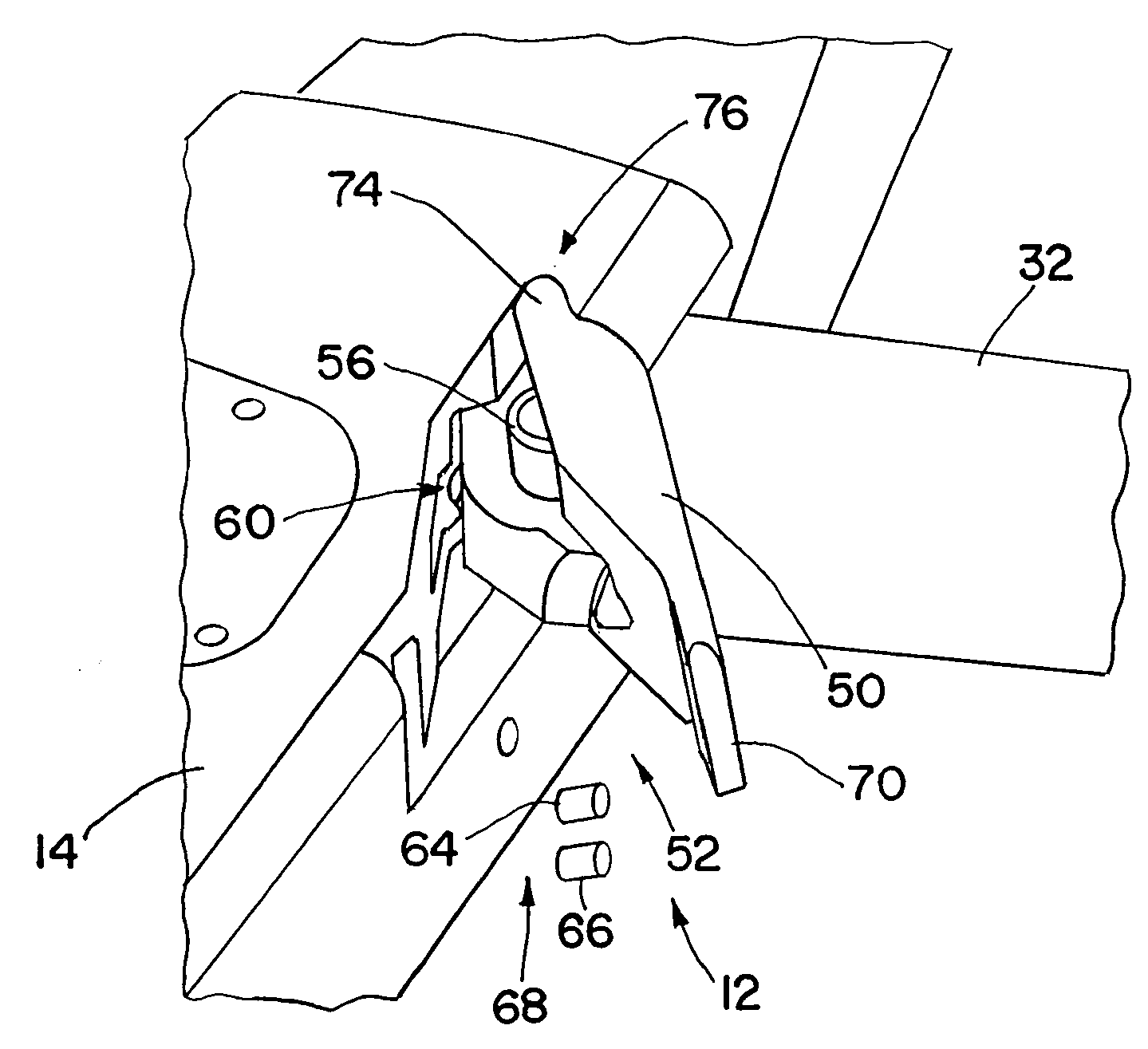
[0024]An aircraft has a flight termination system that allows flight of an unmanned aircraft to be quickly and efficiently terminated. The flight termination system separates one of the control surfaces of the aircraft, such as a wing, from a fuselage of the aircraft, while one or more other control surfaces connected to the fuselage. The separation may be accomplished by firing one or more explosive bolts to release a clamp that connects the control surface to the fuselage. The separation causes an asymmetry in configuration that results in a rapid crash of the aircraft. The flight termination system causes termination to be effected in small flight footprint, without use of powerful explosives, and without a large cost in weight or volume. The flight termination system may be used in unpowered or powered aircraft, but is particularly useful in winged glide aircraft where no fuel supply can either be cut off or detonated to cause flight termination.

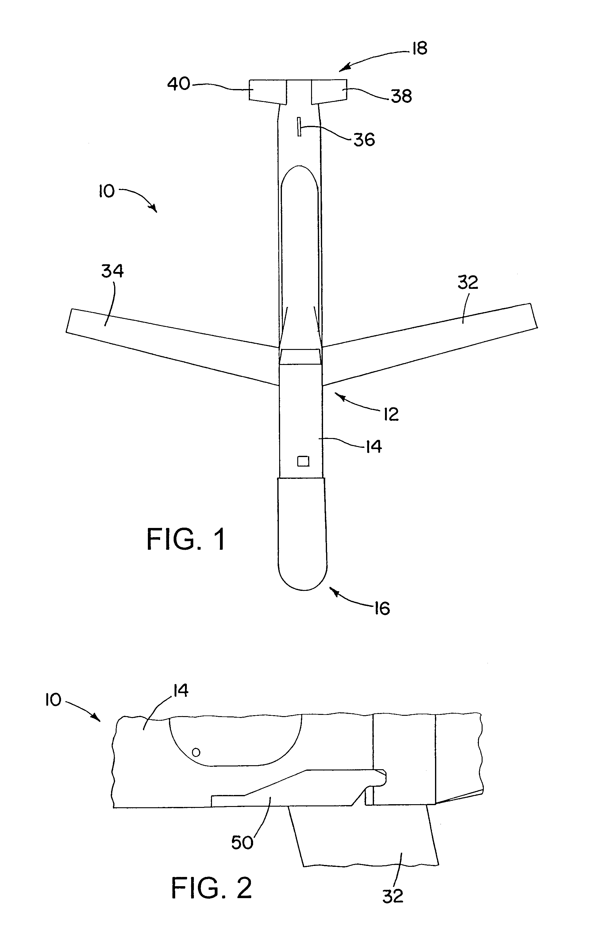
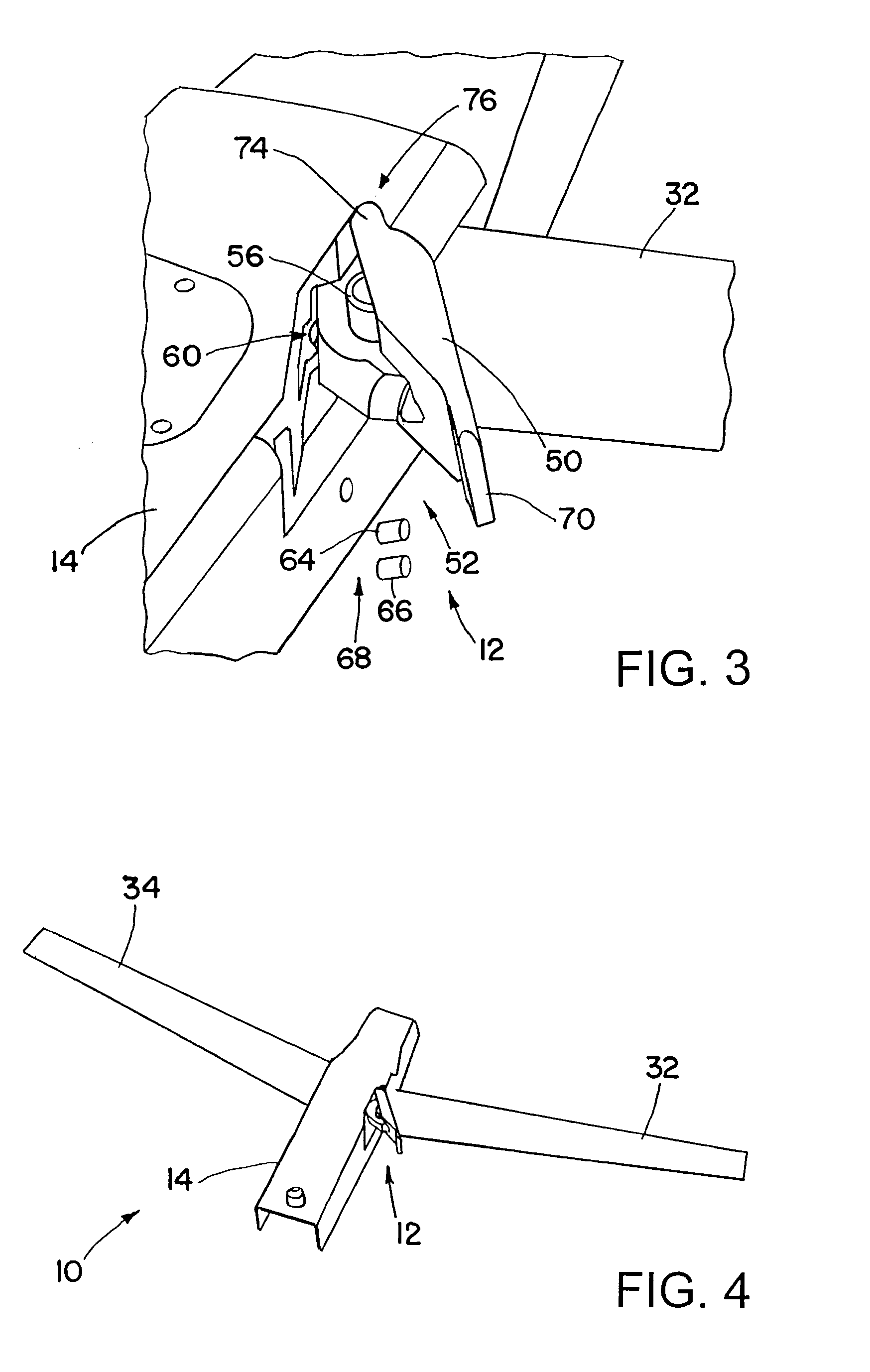
[0025]FIG. 1 shows an aircraft 10...


PUM


Abstract

An aircraft has a flight termination system that allows flight of an unmanned aircraft to be quickly and efficiently terminated. The flight termination system separates one of the control surfaces of the aircraft, such as a wing, from a fuselage of the aircraft, while one or more other control surfaces connected to the fuselage. The separation may be accomplished by firing one or more explosive bolts to release a clamp that connects the control surface to the fuselage. The separation causes an asymmetry in configuration that results in a rapid crash of the aircraft. The flight termination system causes termination to be effected in small flight footprint, without use of powerful explosives, and without a large cost in weight or volume. The flight termination system may be used in unpowered or powered aircraft.

Description

GOVERNMENT RIGHTS[0001]This invention was made with government support under Government Contract FA8681-06-C-0152, SDB Increment II Risk Reduction. The government may have certain rights in this invention.BACKGROUND OF THE INVENTION[0002]1. Technical Field of the Invention[0003]The invention is in the field of flight termination systems for terminating aircraft flights.[0004]2. Description of the Related Art[0005]Prior flight termination systems have utilized highly explosive pyrotechnic charges to break an aircraft into pieces to interrupt flight. Other systems have disrupted flight using a combination of an aerodynamic disrupter such as an air brake, and control fin deflections. Powered flight systems have had flight terminated by cutting off fuel to a flight motor, or by detonating the fuel.[0006]Improvements in the area of flight termination systems would be desirable.SUMMARY OF THE INVENTION[0007]A flight termination system for an aircraft accomplishes flight termination by she...

Claims


Application Information

Patent Timeline
IPC IPC(8): B64C31/02F42B3/00B64C3/00
CPCB64C1/32B64C3/56B64C19/00F42B15/36F41H11/02F42B10/48B64C39/024B64U30/14B64U40/10B64U20/60B64U10/25
Inventor DIETRICH, MARK C.TREPANIER, CHARLES N.WERCH, TIMOTHY R.
Owner RAYTHEON CO
Why Eureka
Try Eureka