Apparatus and Method for Reducing Glare in Images

a technology of glare reduction and images, applied in the field of computational photography, can solve the problems of reducing image contrast and glare, and achieve the effects of reducing glare artifacts, reducing image contrast, and reducing glar

Inactive Publication Date: 2009-11-05
MITSUBISHI ELECTRIC RES LAB INC
View PDF3 Cites 116 Cited by
  • Summary
  • Abstract
  • Description
  • Claims
  • Application Information

AI Technical Summary

Benefits of technology

[0008]Glare reduces image contrast and arises from multiple scattering of light inside the camera's body and lens optics. Therefore, the embodiments of the invention provide an apparatus and method for reducing glare. A 4D ray-space between the camera lens and sensor is analyzed statistically to reduce glare artifacts. In the 4D ray-space, glare behaves as high frequency noise and can be reduced by replacing intensities values of bright outlier pixels with intensities from adjacent pixels, using linear interpolation.
[0009]The invention provides a practical solution to analyze the 4D statistics without significantly compromising the resolution of the output image. Unlike conventional light field cameras, the invention does not need to reversibly encode the spatial structure of the 4D ray-space. Hence, the constraints for the camera are simple.
[0010]Although diffuse scattering of the lens introduces non-removable 4D low-frequency glare, the invention produce useful solutions in a variety of common scenarios. The invention can handle images taken while the lens is directly exposed to the sun, and images taken without a hood. The invention can reduce the effect of dust on the lens and reduces loss of contrast due to camera body reflections.
[0011]In one embodiment, a mask with pin-holes is place in close proximity, e.g., ≈1.2 mm, to the sensor. The pin-holes disperse the incoming light rays over small circular areas of pixels of the sensor directly underneath the pin-holes. Statistics of pixel intensities values are determined in an input image and pixels are replaced according to the statistics to produce an output image with reduced glare.

Problems solved by technology

Glare reduces image contrast and arises from multiple scattering of light inside the camera's body and lens optics.

Method used


Image

  • Apparatus and Method for Reducing Glare in Images
  • Apparatus and Method for Reducing Glare in Images
  • Apparatus and Method for Reducing Glare in Images

Examples


Embodiment Construction

[0021]Camera

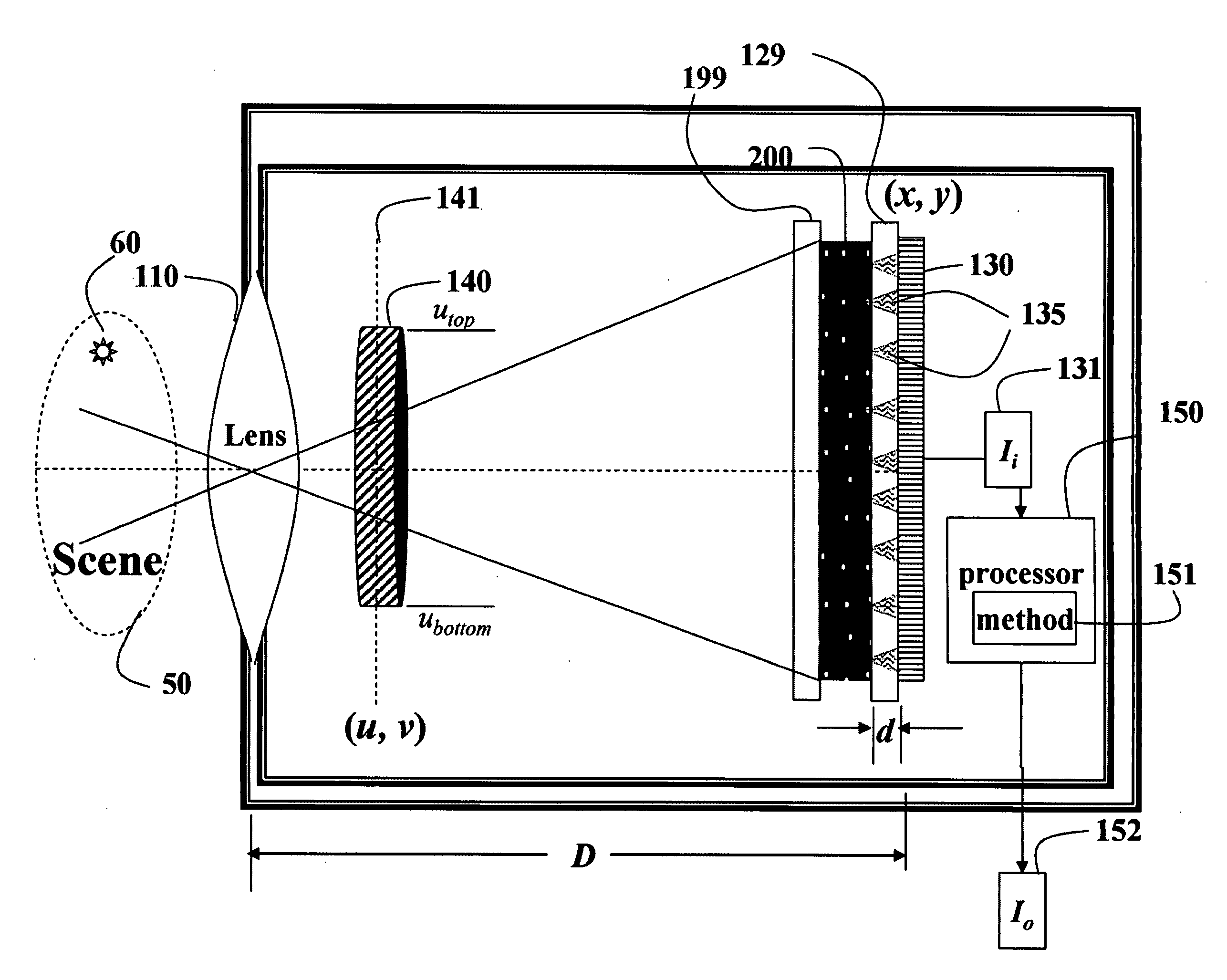
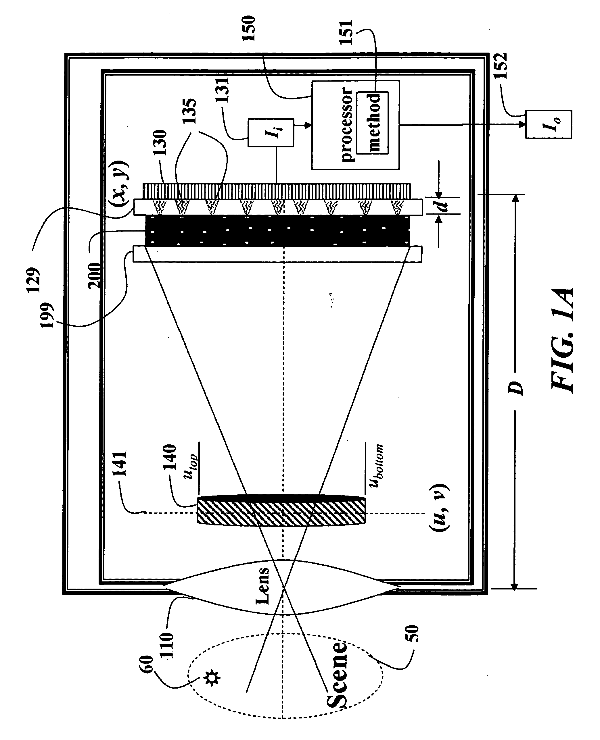
[0022]FIG. 1A shows a camera 100 for reducing glare according to an embodiment of our invention. The camera acquires an input image 131 of a scene 50 including a bright light source 60. The camera includes a lens 110, a high-frequency mask 200, and a sensor 130 having sensor pixels. The mask is placed at a distance of about 1.2 mm from the sensor and coplanar with the sensor. The camera can also include an aperture 140. The sensor is coupled to a processor 150, which processes the input image Ii 131 acquired by the sensor using our method 151. An output image I0 152 has reduced glare.

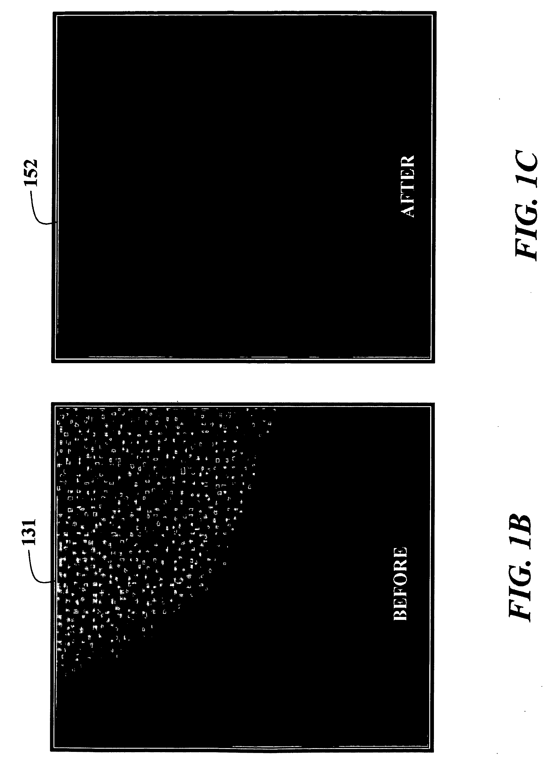
[0023]FIGS. 1B and 1C dramatically shows the before and after effects of our invention. As shown in FIG. 1B, the glare is evident as isolated bright pixels due to our mask with randomly placed pin-holes. The glare pixels have clearly been separated from the rest of the image. These pixels can now be easily be identified as being ‘outliers’ using some thresholding technique, and replaced usin...


PUM


Abstract

Glare is reduced by acquiring an input image with a camera having a lens and a sensor, in which a pin-hole mask is placed in close proximity to the sensor. The mask localizes the glare at readily identifiable pixels, which can then be filtered to produce a glare reduce output image.

Description

FIELD OF THE INVENTION [0001]This invention relates generally to computational photography, and more particularly to reducing glare in images acquired by cameras.BACKGROUND OF THE INVENTION [0002]It is difficult to acquire a clear image of a scene that includes a bright light source in or near the field of view the camera. Glare reduces contrast and causes image fog and large area ghosts. Glare is hard to avoid and disrupts every optical system, including the human eye. Glare can be due to Fresnel reflection at lens surfaces, and diffusion in lenses. However, the two are often indistinguishable in an image.[0003]International Organization for Standardization (ISO) standard 9358, 1994, describes a procedure for measuring glare and defines a veiling glare index as a ratio of the luminance in the center of a black target to the luminance of the surrounding large area uniform illuminant.[0004]McCann et al. measured glare in multi-exposure high-dynamic range (HDR) images, McCann et al., ...

Claims


Application Information

Patent Timeline
Patent Type & Authority Applications(United States)
IPC IPC(8): G02B27/00H04N5/217H04N5/225
CPCG02B27/0018H04N17/002H04N5/3572H04N5/2254H04N23/811H04N23/55H04N25/61H04N23/843
Inventor RASKAR, RAMESHWILSON, CYRUS A.AGRAWAL, AMIT K.
Owner MITSUBISHI ELECTRIC RES LAB INC
Why Eureka
Try Eureka