Technique for providing interconnection between communication networks

Inactive Publication Date: 2009-11-05
ECE TELECOM LTD
View PDF11 Cites 50 Cited by
  • Summary
  • Abstract
  • Description
  • Claims
  • Application Information

AI Technical Summary

Benefits of technology

[0020]The object of the present invention is providing a simple technique for connecting Ethernet and/or VPLS networks, that would be capabl

Problems solved by technology

A multicast or broadcast traffic introduced into Ethernet network with a layer 2 loop, will indefinitely keep circulating in the network, and might steadily consume more and more resources until the network overloads.
The financial costs associated with unexpected downtime is leading service providers to build fault-tolerant networks.
A drawback of this method is the need to maintain xSTP signaling interaction between the switches.
This is especially complicated when the dual homing connectiv

Method used


Image

  • Technique for providing interconnection between communication networks
  • Technique for providing interconnection between communication networks
  • Technique for providing interconnection between communication networks

Examples


Example

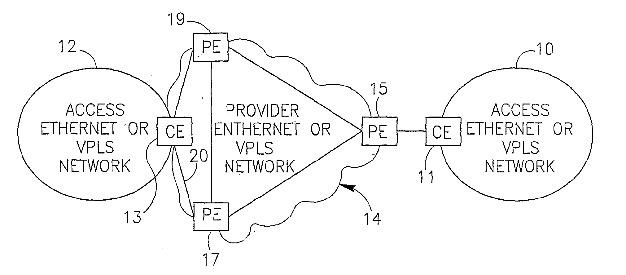
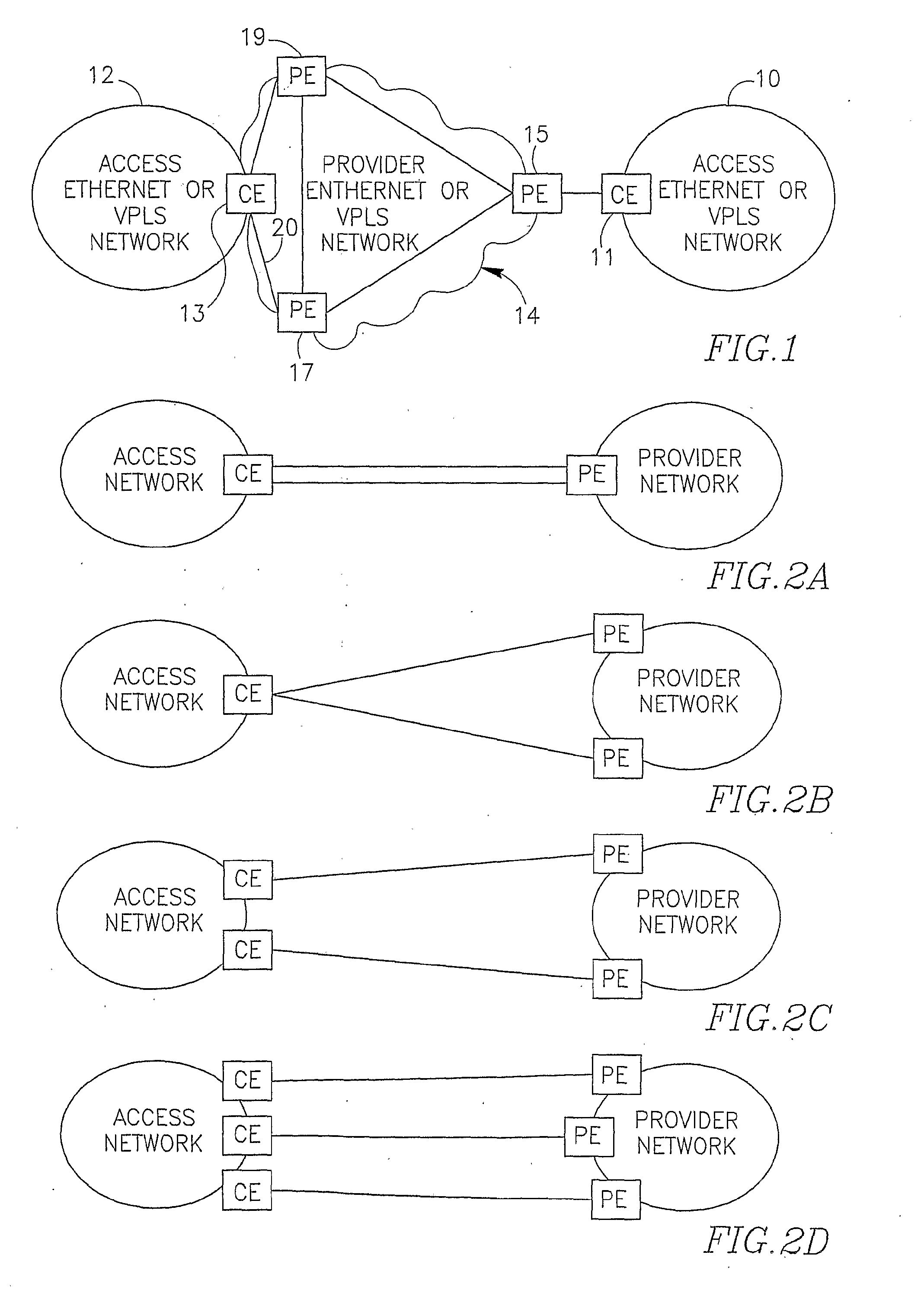
[0068]FIGS. 1 and 2 have been described in the background of the invention.

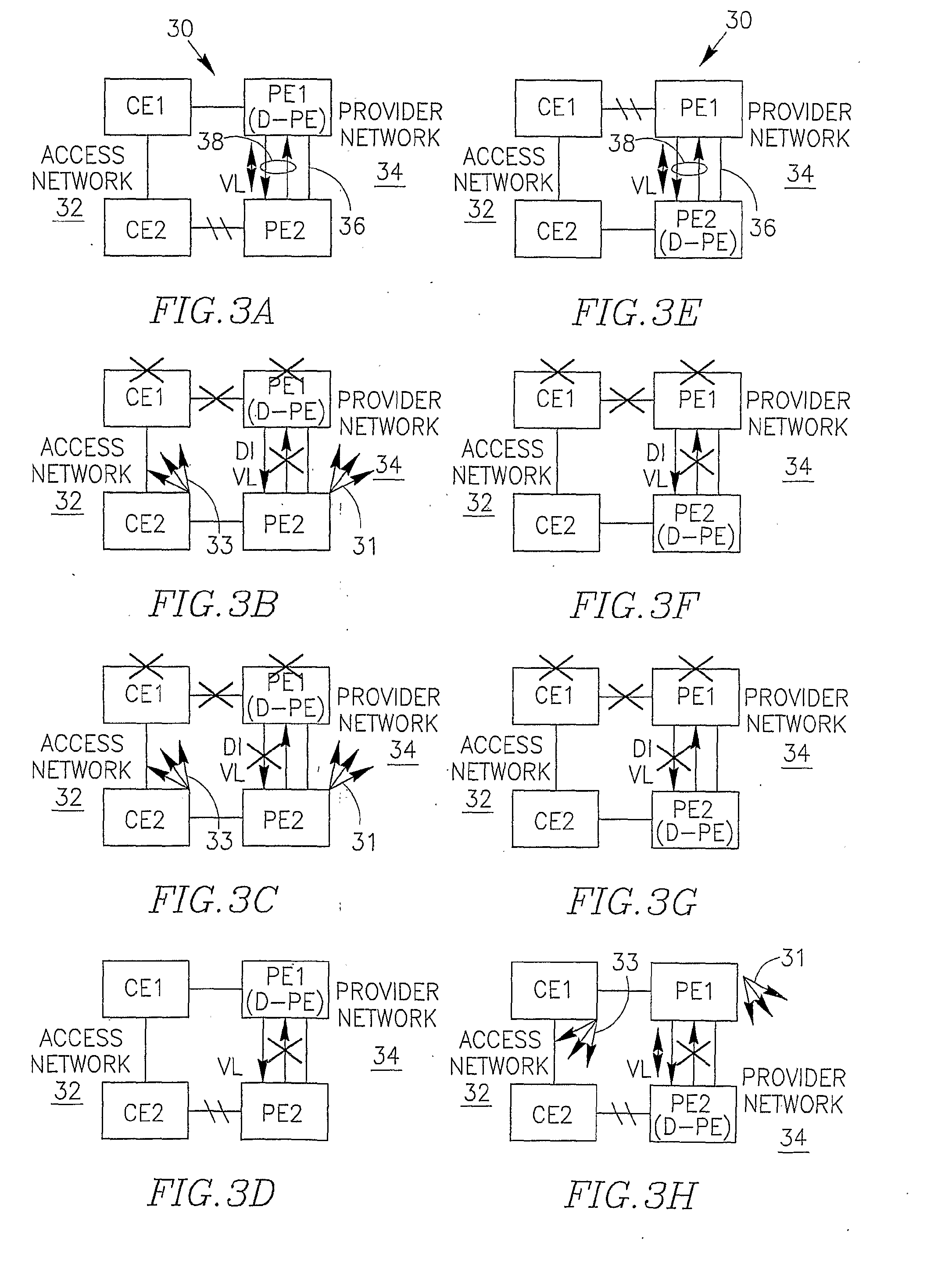
[0069]FIG. 3a schematically illustrates a steady-state operation of an exemplary dual-homing configuration 30 connecting an access Ethernet-based network 32 to a provider Ethernet-based or VPLS network 34 via edge customer nodes CE1, CE2 and edge provider nodes (let them be called peer nodes) PE1, PE2, where CE1 (CE2) is directly connected to PE1 (PE2) via a physical link or spoke PW. PE1 and PE2 may also be connected for the purpose of exchanging customer traffic (in case of a VPLS provider network, there is a PW 36 per VPN between PE1 and PE2). The nodes CE1, CE2 in the access network 32 are connected via a traffic line within the access network, to visualize that if both CE-PE connections are forwarding, then a layer 2 loop will occur in the access network which might not be running xSTP (as is typically the case if the access network is a VPLS network). In such cases the technique proposed by the Inventor...


PUM


Abstract

Technique for interconnecting a first communication network and a second communication network, for example layer 2 Ethernet networks, which uses a fully or partially redundant dual homing configuration. The configuration includes: at least three network elements where at least two of them are peer elements belonging to the second network, and at least two traffic lines respectively associated with the peer elements and connecting the first and the second networks via the three network elements. The technique comprises establishing a bi-directional signaling between the peer elements and, based on the signaling information, deciding which traffic line should forward the traffic.

Description

FIELD OF THE INVENTION [0001]The invention relates to a technique for interconnecting communication networks, more particularly for providing a traffic protecting though loop free interconnection between layer 2 Ethernet and / or VPLS-packet networks.BACKGROUND OF THE INVENTION [0002]An Ethernet network is composed of Ethernet switches connecting local area network (LAN) or IEEE 802.1Q virtual LAN (VLAN) segments containing end stations. A switch forwards packets between its interfaces (ports) based on media access control (MAC) destination address contained in each packet. An incoming packet may be forwarded to one or more outgoing ports, where the latter case is referred to as multicasting or broadcasting.[0003]FIG. 1 illustrates one possible example of inter-network connectivity where a customer access network (10 or 12) is connected to a provider network (14) via switches referred to as gateway customer edge (CE) switches (11 or 13) and gateway provider edge (PE) switches 15 or 17...

Claims


Application Information

Patent Timeline
IPC IPC(8): H04L12/56H04L45/18H04L45/24
CPCH04L12/462H04L12/4641H04L45/04H04L45/68H04L45/22H04L45/28H04L45/48H04L45/18
Inventor NAKASH, SHELL
Owner ECE TELECOM LTD
Why Eureka
Try Eureka