Ultrasonic measurement apparatus
- Summary
- Abstract
- Description
- Claims
- Application Information
AI Technical Summary
Benefits of technology
Problems solved by technology
Method used
Image

Examples
example 1
[0075]Hereinafter, in a first example, reference will be made to a method of measuring the elastic property of a sample (an object to be measured) by compressing the sample.
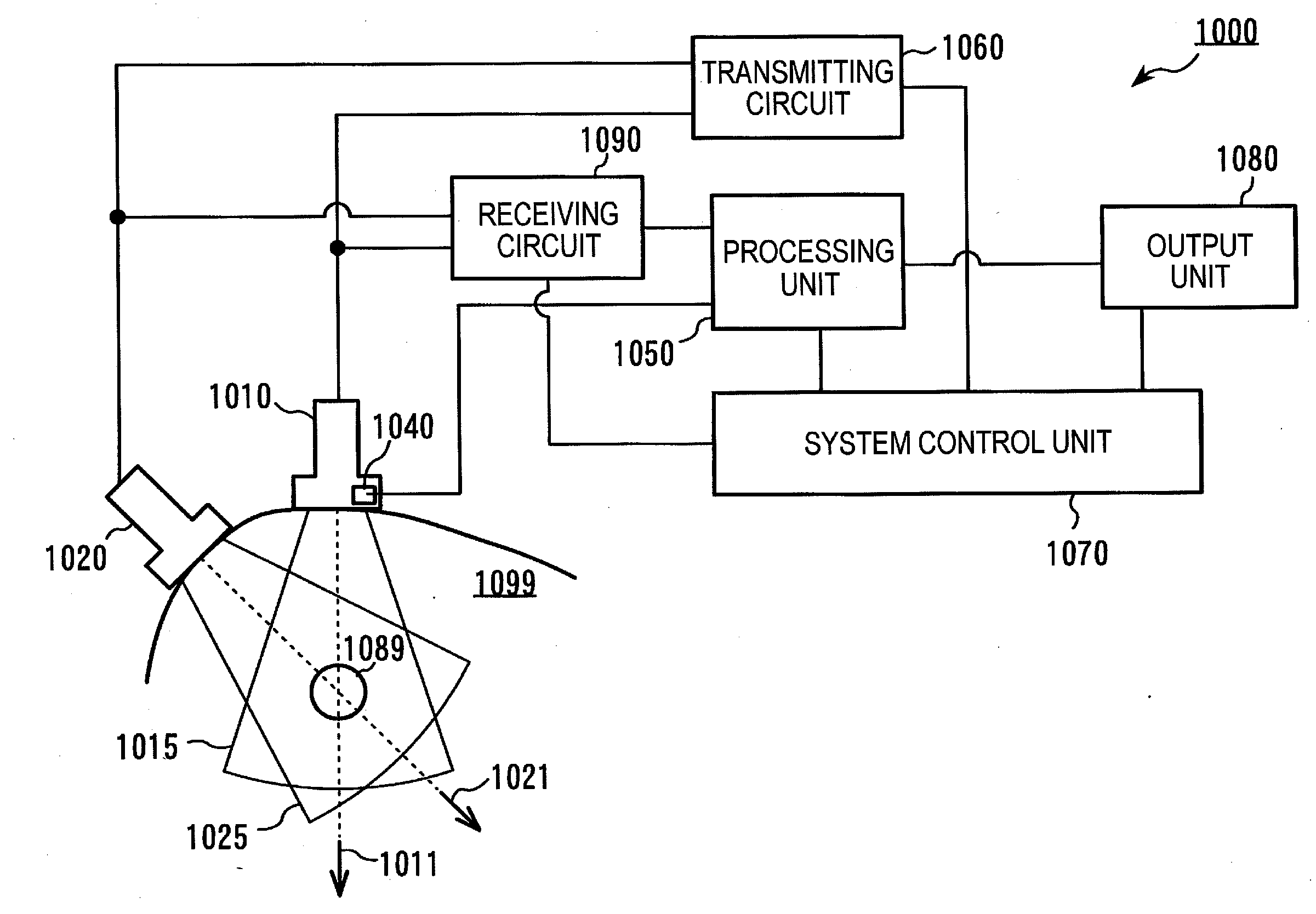
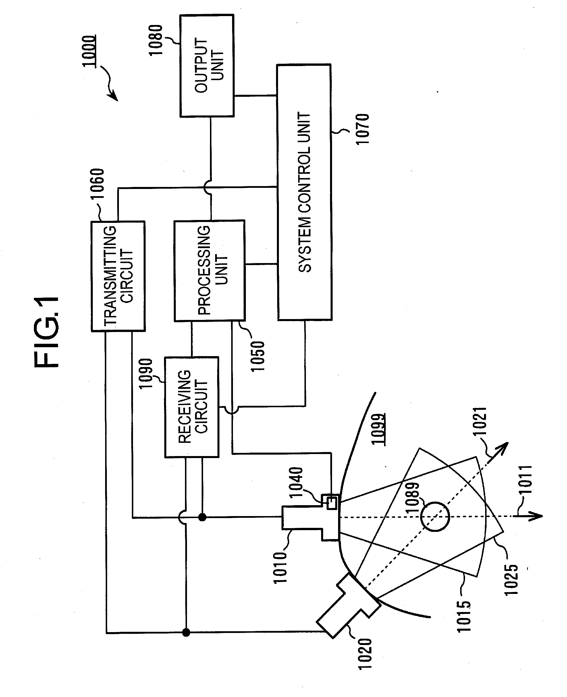
[0076]FIG. 3 is a schematic view of an ultrasonic measurement apparatus according to the first example. The flows of signals will be described below by using FIG. 3. The ultrasonic measurement apparatus is provided with a plurality of ultrasonic probes 1a, 1b, 1c, a transmitting circuit system 6, a receiving circuit system 7, a probe position processing system 8, a tomographic signal processing system 9, a displacement signal processing system 10, an image processing system 11, a image display device 12, a system control unit 13, and a compression data processing unit 17. Here, note that the displacement signal processing system 10 in FIG. 3 corresponds to the processing unit in the above-mentioned embodiment.
[0077]In FIG. 3, an ultrasonic wave transmitting instruction is forwarded to the transmitting circuit sys...
example 2
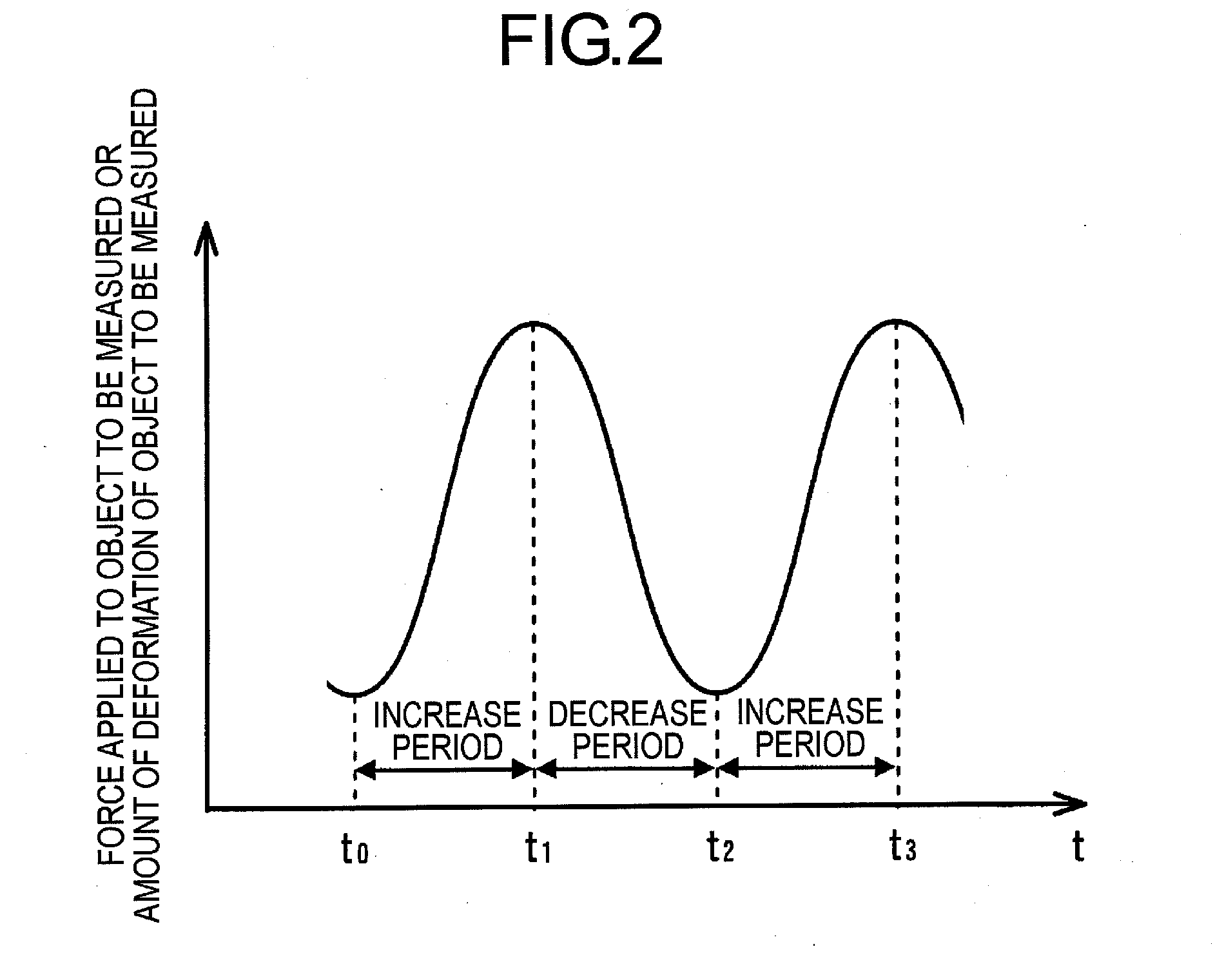
[0103]In a second example, reference will be made to a technique of measuring a strain of a sample according to a method which is different from the first example. In the first example, the strain of the sample is measured by compressing the sample, but in case where a sample moves voluntarily on its own, points of measurement in the sample also move, so the measurement of a strain in the sample can be carried out without performing a compressing operation. For example, a heart and its surrounding portions are caused to deform in a periodic manner in accordance with the movement of cardiac muscle, so a compressing operation from the outside is unnecessary. In such a case, the measurement of a strain in the heart or its surrounding portions is performed without moving the ultrasonic probes 1a, 1b, 1c in FIG. 3. In addition, the methods of measurement and calculation are quite the same as the first example, and similar effects can be achieved.
example 3
[0104]In a third example of the present invention, reference will be made to an example in which the measurement of an elastic modulus distribution is performed by using a compressing device which is different from the one used in the first example. FIG. 7 is a view illustrating a sample and its surroundings using this third example. Ultrasonic probes 1a, 1b, 1c, position sensors 5a, 5b, 5c, and a sample 2 are arranged similar to the first example, but in this third example, a compressing device 14 is arranged besides the probes. The entire system of an ultrasonic measurement apparatus of this third example is similar to that of the first example (FIG. 3). At the time of measurement, the sample is compressed by the compressing device 14, and ultrasonic signals before and after the compression are acquired by the ultrasonic probes 1a, 1b, 1c. In addition, arranging the individual ultrasonic probes 1a, 1b, 1c and the compressing device 14 so as to have symmetry with one another provid...
PUM
 Abstract
Description
Claims
Application Information
 - R&D
- Intellectual Property
- Life Sciences
- Materials
- Tech Scout
- Unparalleled Data Quality
- Higher Quality Content
- 60% Fewer Hallucinations
Browse by: Latest US Patents, China's latest patents, Technical Efficacy Thesaurus, Application Domain, Technology Topic, Popular Technical Reports.
© 2025 PatSnap. All rights reserved.Legal|Privacy policy|Modern Slavery Act Transparency Statement|Sitemap|About US| Contact US: help@patsnap.com