Movement assisting device and movement assisting method

Inactive Publication Date: 2009-11-05
PANASONIC CORP
View PDF14 Cites 35 Cited by
  • Summary
  • Abstract
  • Description
  • Claims
  • Application Information

AI Technical Summary

Benefits of technology

[0028]According to such configuration, the user can more easily perform the movement acco

Problems solved by technology

In the prior art, however, the movement can only be assisted in the direction and with the force instructed by the control means or defined in advance, when assisting the bend and the extension of the joint of the user.
Thus, the muscle or the joint of the user might get injured if the mov

Method used


Image

  • Movement assisting device and movement assisting method
  • Movement assisting device and movement assisting method
  • Movement assisting device and movement assisting method

Examples


Example

First Embodiment

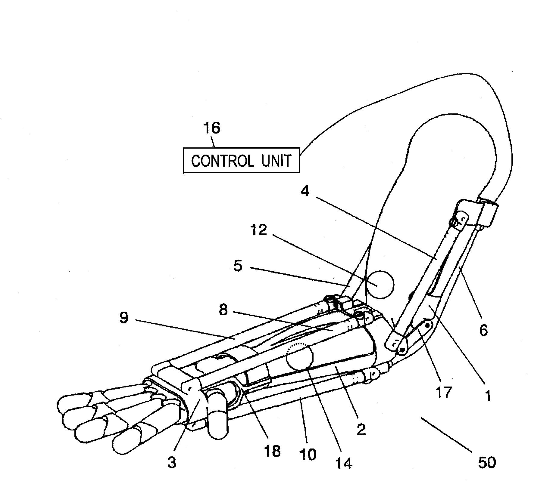
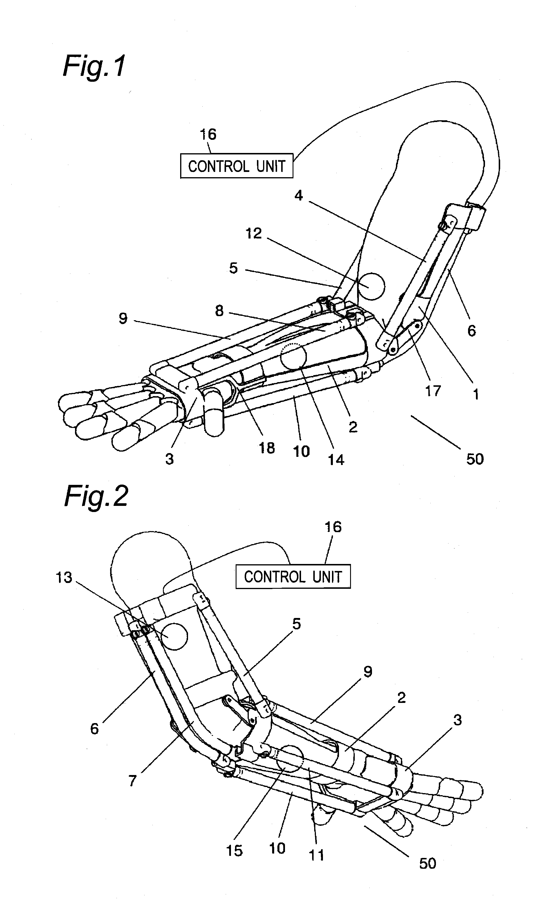
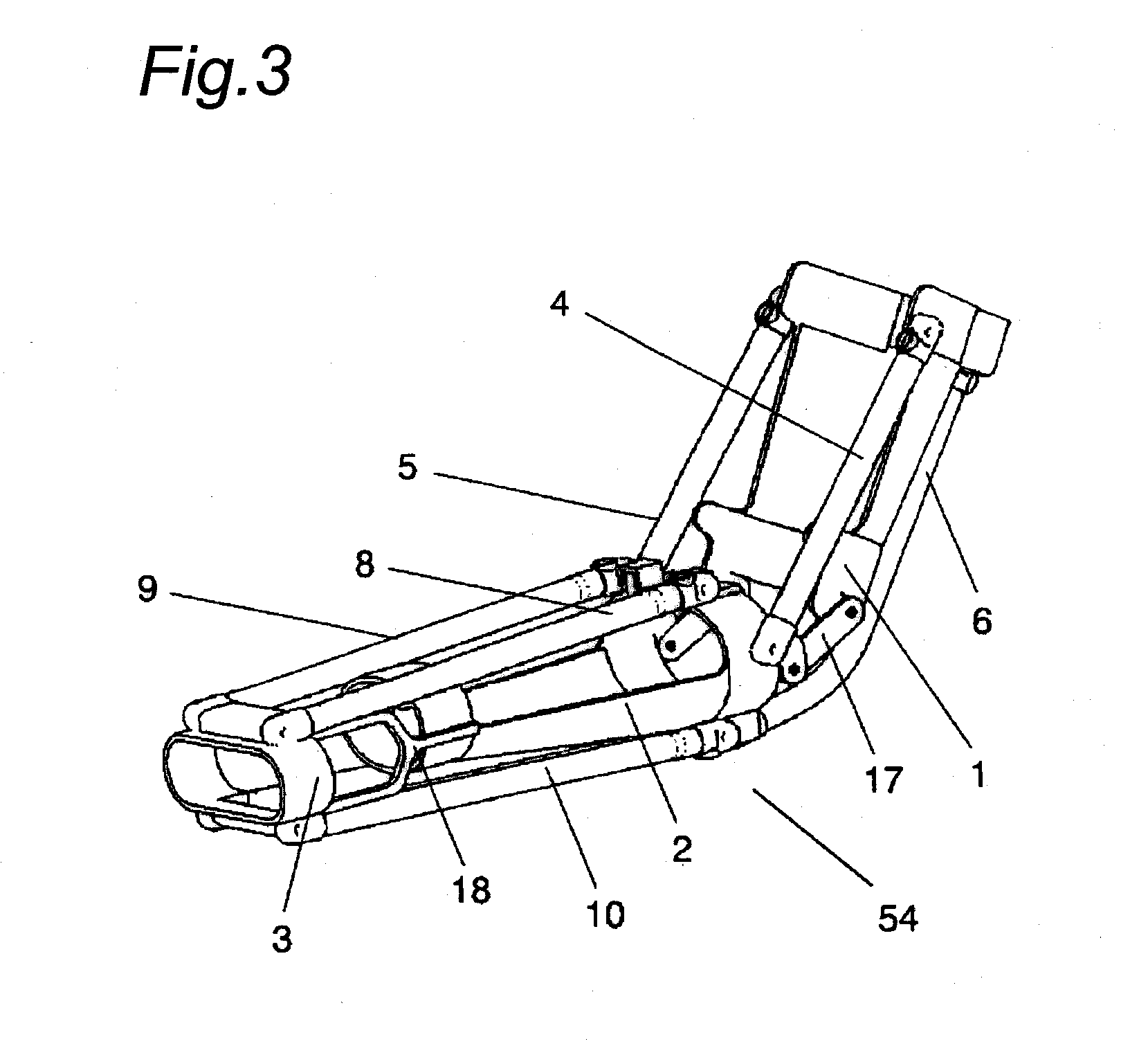
[0055]FIG. 1 is a perspective view showing a state in which a movement assisting device 50 according to a first embodiment of the present invention is attached to the arm, and FIG. 2 is a perspective view of the movement assisting device 50 in the state shown in FIG. 1 seen from the rear side. FIG. 3 is a perspective view of an actuator unit 54 portion of the movement assisting device 50.

[0056]As shown in FIG. 1 to FIG. 3, the movement assisting device 50 according to the first embodiment of the present invention is an attachment arranged across the elbow joint of the user, and includes a cuff 1 attached to the upper arm and a cuff 2 attached to the forearm, a rubber artificial muscle 4 and a rubber artificial muscle 5 arranged in pairs while being suspended between the cuff 1 and the cuff 2 to aid the movement in the bending direction of the elbow, as well as, a rubber artificial muscle 6 and a rubber artificial muscle 7 arranged in pairs at a position where the for...

Example

Second Embodiment

[0083]A movement assisting device 60 according to a second embodiment of the present invention will now be described. FIG. 8 is a view showing a configuration of the movement assisting device 60.

[0084]As shown in FIG. 8, the movement assisting device 60 includes a sensor unit 62, an actuator unit 64, and a control unit 66. The movement assisting device 60 differs from the movement assisting device 50 in the first embodiment in that the sensor unit 62 is attached to an arm opposite to the arm attached with the actuator unit 64.

[0085]According to such configuration, the movement assisting device 60 enables the control unit 66 to detect the movement of the arm attached with the sensor unit 62, and operate the other arm with the rubber artificial muscle of the actuator unit 64 so as to assist the relevant movement.

[0086]According to such configuration, rehabilitation effective for users who have become paralyzed on one side of the body can be performed by using the move...

Example

Third Embodiment

[0096]A movement assisting device 70 according to a third embodiment of the present invention will now be described.

[0097]FIG. 10 is a view showing a configuration of the movement assisting device 70 according to the third embodiment of the present invention.

[0098]As shown in FIG. 10, the movement assisting device 70 includes a sensor unit 72, an actuator unit 74, and a control unit 76 connected to the sensor unit 72 and the actuator unit 74.

[0099]The movement assisting device 70 differs the most from the movement assisting device 50 according to the first embodiment and the movement assisting device 60 according to the second embodiment in that the sensor unit 72 and the actuator unit 74 are attached to different people. In the present embodiment, an example where the movement assisting device 70 includes a plurality of actuator units 74 with respect to one sensor unit 72 is shown.

[0100]The sensor unit 72 of the movement assisting device 70 is attached to an arbitra...


PUM


Abstract

A movement assisting device including a plurality of attachments to be attached over a joint of a user; an actuator suspended between the plurality of attachments; a sensor, attached to the user, for detecting movement of a muscle; and a control unit for controlling the actuator based on the movement of the muscle detected by the sensor is provided.

Description

TECHNICAL FIELD[0001]The present invention relates to a movement assisting device and a movement assisting method for assisting the movement of elbow, wrist, knee, or the like of a human body using an actuator.BACKGROUND ART[0002]Various training devices for regaining the muscle strength of each part of hands and legs, torso, neck or the like have been conventionally developed for patients having disability in motor function.[0003]Various devices such as walk assisting device, stair elevating lift device, or carrying lift device for assisting daily movement of an elderly who has lost physical strength, and alleviating physical strain on the caretaker have been developed in an aim of aiding muscle strength.[0004]In such devices, a technique for aiding the muscle strength of the user by being worn is proposed in Japanese Laid-Open Patent Publication No. 2001-286519 and Japanese Laid-Open Patent Publication No. 2001-276101.[0005]First, the device disclosed in Japanese Laid-Open Patent ...

Claims


Application Information

Patent Timeline
IPC IPC(8): A61F2/66A61F2/72A61B5/103
CPCA61H1/0274A61H2201/5058A61H2201/5007A61H2201/165A61F2/58A61F2/72A61F5/00A61H1/0277A61H1/024A61B5/389A61H1/02
Inventor UEDA, KEISUKEFUJIMOTO, HIROMICHISHIROGAUCHI, GO
Owner PANASONIC CORP
Why Eureka
Try Eureka