Automated voltage analysis in an electrical system using contextual data

a technology of contextual data and automatic analysis, applied in the field of utility systems, can solve the problems of affecting the efficiency of the motor, affecting the viability of the motor, and elevated voltage levels that are just as damaging to the viability of the motor, and achieve the effect of quick respons

Active Publication Date: 2009-11-05
SCHNEIDER ELECTRIC USA INC
View PDF4 Cites 84 Cited by
  • Summary
  • Abstract
  • Description
  • Claims
  • Application Information

AI Technical Summary

Benefits of technology

[0012]Advantages and benefits over existing techniques include continual evaluations, quicker responsivene

Problems solved by technology

Facilities that comprise electrical systems may encounter voltage levels on their equipment that deviate from nominal values.
MG 1 specifically points out that elevated voltage levels are just as damaging to the viability of a motor as low voltage levels (not to mention the adverse impact to the motor's efficiency).
For example, when the equipment is an induction motor, at full load current, a ±10% voltage deviation can substantially increase the core losses of the motor resulting in overheating and potential damage to the motor's insulation over time.
When starting a motor during severe undervoltage conditions, the developed torque may not be sufficient to allow the motor to come up to speed.
Because motors are designed to operate most efficiently at their nameplate voltage rating, operating outside of a motor's recommended voltage rating will also decrease the motor's performance due to the introduction of additional losses into the electrical system.
By way of another example, when the equipment comprises fluorescent lamps, deviating outside of the recommended voltage range may have negative consequences including shortened lamp and/or ballast life, reduced efficacy, potential starting issues, and overheating.
This “unawareness” is primarily due to the lack of experience

Method used


Image

  • Automated voltage analysis in an electrical system using contextual data
  • Automated voltage analysis in an electrical system using contextual data
  • Automated voltage analysis in an electrical system using contextual data

Examples


Embodiment Construction

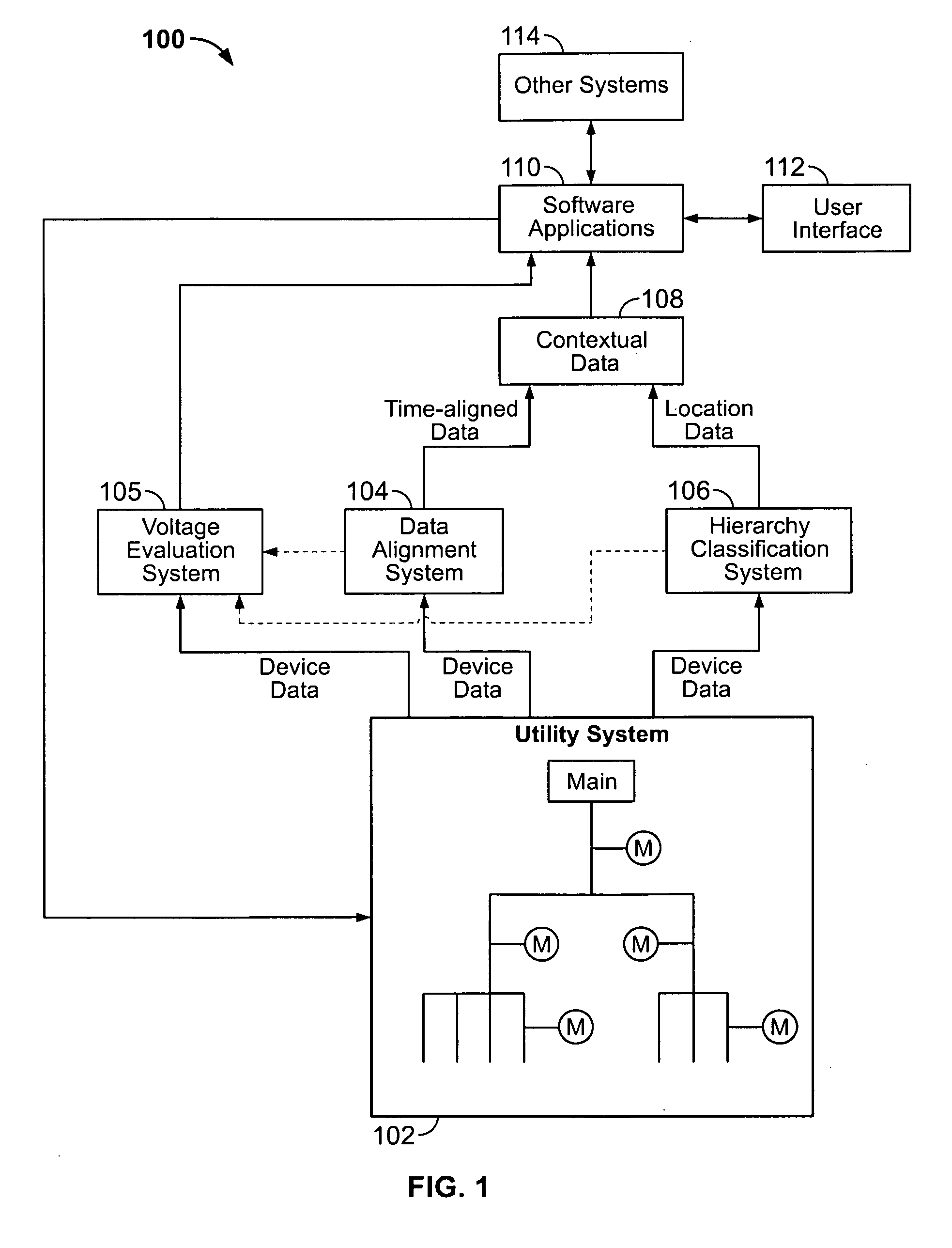
[0028]Turning now to FIG. 1, an automated data integrated monitoring system 100 is generally shown. An electrical system 102 having multiple intelligent electronic devices (hereafter “IEDs”) designated by the letter M provides data from each IED M that is communicated to an automated data alignment system 104 and an automated hierarchy classification system 106. As used herein, an IED refers to any system element or apparatus with the ability to sample, collect, or measure one or more operational characteristics or parameters of an electrical system 102. The data is aligned automatically in temporal or pseudo-temporal context in the automated data alignment system 104 and produces data that is temporally aligned such that it represents the data when it was actually seen simultaneously by the monitoring devices M in the power monitoring system 102. The hierarchy classification system 106 automatically learns the hierarchy of monitoring devices present in the utility system 102 and th...


PUM


Abstract

A voltage analysis algorithm for automatically determining anomalous voltage conditions in an electrical system monitored by a plurality of intelligent electronic devices (IEDs) and automatically making recommendations for ameliorating or eliminating the anomalous voltage conditions. The electrical system hierarchy is determined automatically or manually, and the algorithm receives voltage data from all capable IEDs. The voltage data is temporally aligned or pseudo-aligned to place the voltage data in both spatial and temporal context. The algorithm determines anomalous voltage conditions systemically by comparing measured voltage values against nominal or expected ones across the system. Based on the spatial and temporal context of the IEDs, the algorithm automatically identifies a source of the voltage deviation in the hierarchy, and recommends a modification associated with the source for mitigating the anomalous voltage condition. The algorithm checks its recommendation to determine any adverse effects on the electrical system and adjusts the recommendation accordingly.

Description

FIELD OF THE INVENTION[0001]Aspects disclosed herein relate generally to utility systems, and, in particular, to a method for automatically analyzing voltage data in a utility system.BACKGROUND[0002]Facilities that comprise electrical systems may encounter voltage levels on their equipment that deviate from nominal values. For example, for an induction motor rated at 460 volts, an excessive voltage level above 500 volts may be present. End-users may errantly believe that if low voltage levels are unacceptable, then high voltage levels must be acceptable. However, the National Electrical Manufacturers Association (NEMA) Standards Publication No. MG 1 specifically points out that elevated voltage levels are just as damaging to the viability of a motor as low voltage levels (not to mention the adverse impact to the motor's efficiency). Other types of loads besides motors would also experience reduced efficiencies and shortened life due to extensive voltage deviations (e.g., lighting sy...

Claims


Application Information

Patent Timeline
IPC IPC(8): G01R31/00
CPCH02J3/00
Inventor BICKEL, JON A.
Owner SCHNEIDER ELECTRIC USA INC
Why Eureka
Try Eureka