
Striking tool

a technology of tools and tools, applied in the field of striking tools, can solve the problems of excessive force on the workforce and tools, potential loss and/or theft of tools, and time-consuming and energy-consuming demolition, and achieve the effect of enhancing forces

Inactive Publication Date: 2009-11-12
ROBERT ADAMS +1
View PDF6 Cites 17 Cited by
  • Summary
  • Abstract
  • Description
  • Claims
  • Application Information

AI Technical Summary

Benefits of technology

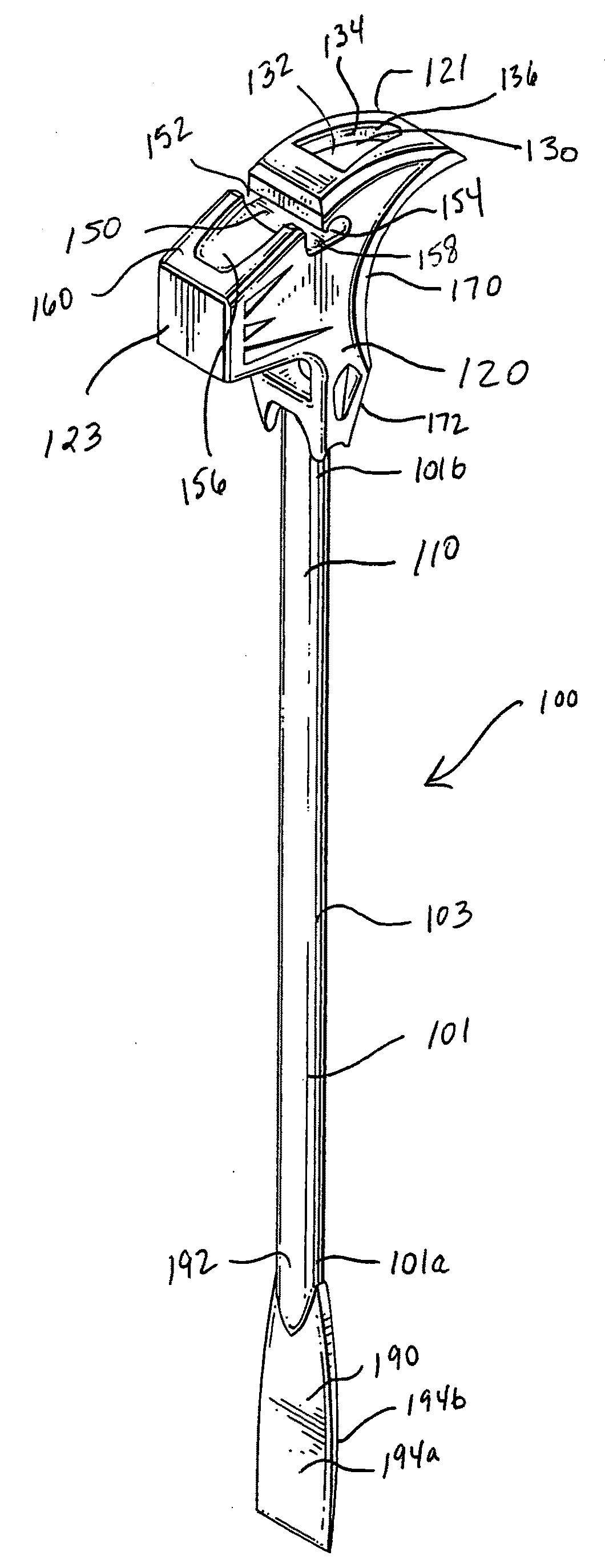
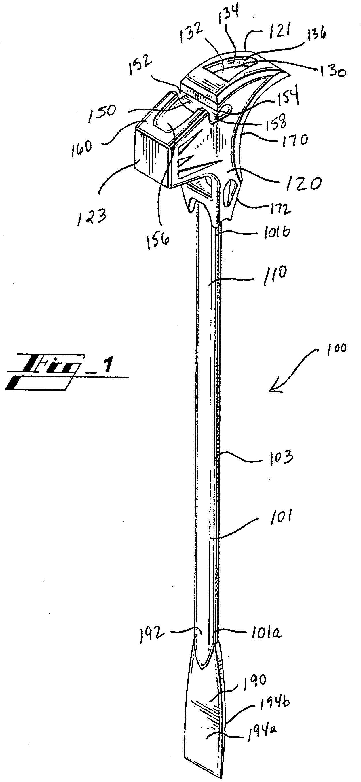
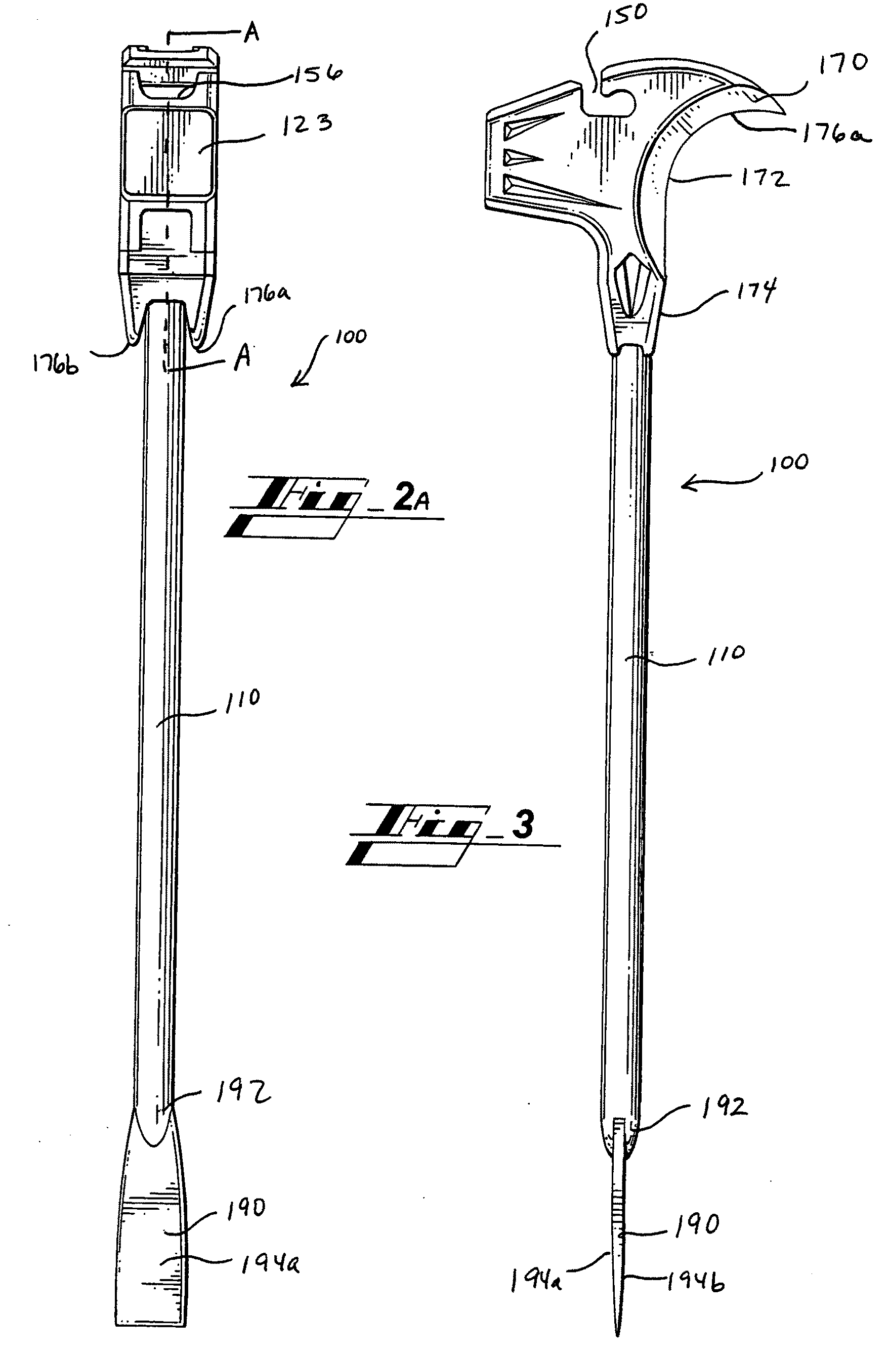
[0007]Briefly described, in an exemplary embodiment, the striking tool of the present disclosure overcomes the above-mentioned disadvantages and meets the recognized need for such a tool by providing a steel hammer having a head, a striking surface, a nail-pulling tool, a nail-starting tool, a sharpened surface, and including one or more cavity and / or void, and a handle having a strong yet lightweight construction and a chisel tool.
[0008]More specifically, the exemplary striking tool includes a generally extended handle portion with a striking head at a first end of the handle portion, and a chisel at a second end of the handle portion. The handle portion preferably includes a generally broad, flat forward surface adapted to reduce damage caused by overstrikes, i.e. poorly aimed strikes where an impact force is borne by the handle portion. A medial section of the handle portion, however, is generally thin compared to the broad forward surface, whereby a reduction in weight and advantageous balance is provided. A broad rearward surface is preferably also included for stability and strength of the handle portion. Additionally, a chisel or wedge is preferably included at the other end of the handle portion, wherein the chisel portion has a preferably broad front and rearward surface to facilitate effective delivery of prying forces. The handle portion may also include a comfortable grip operable therewith to provide a comfortable and secure gripping surface by which a user may grasp the tool.
[0009]The striking head preferably includes a cavity extending from the rear of the striking head to the rear of the striking face and into the claw zone. The cavity thus preferably defines an upper chamber portion and a lower chamber portion. The chamber portions preferably reduce vibrations caused by strikes, and substantially prevent transmission of vibrations to the handle portion, while further enabling distribution of sufficient mass to safely and reliably allow accurate delivery of forceful strikes without causing excessive strain or fatigue.

Problems solved by technology

Transport of such a collection of tools to a jobsite is a difficult and burdensome task in and of itself, but retaining mobility of such a number of tools while moving about a jobsite during work is disadvantageously time and energy consuming, and involves potential loss and / or theft of tools mislaid during periods of nonuse.
Further, demolition work can be exceedingly hard on workforce members and tools.
Thus, not only does the nature of the work typically require a plurality of tools, each tool is repeatedly subject to high stress conditions and is therefore unlikely to remain capable for peak performance for any extended period of time.
This disadvantage can increase the frequency of tool replacement, and given the plurality of tools necessary, can increase costs.
Coupled with increased labor costs from time-inefficient tool transport and interchange, profit margins for demolition teams can plummet.
Further disadvantages may be realized directly by the workforce members.
That is, in addition to time and material costs, worker performance can be compromised by premature exhaustion as a result of repeated expenditure of energy exchanging between a plurality of heavy tools, and necessarily transporting those tools about the demolition site.

Method used


Image

  • Striking tool
  • Striking tool
  • Striking tool

Examples


Embodiment Construction

[0028]In describing exemplary embodiments of the tool of the present disclosure illustrated in the drawings, specific terminology is employed for the sake of clarity. The claimed invention, however, is not intended to be limited to the specific terminology so selected, and it is to be understood that each specific element includes all technical equivalents that operate in a similar manner to accomplish a similar purpose.

[0029]In that form of the sledge hammer of the present disclosure chosen for purposes of illustration, FIGS. 1-3 show hammer 100 including body 101 and grip 103. Body 101 is preferably formed from a suitable metal, composite, or synthetic material, or the like, defining handle 110 and head 120, and may include grip 103 formed or installed thereon. Grip 103 may be formed from natural or synthetic rubber, plastic, composite, or the like, and may be resilient and / or sculptured or contoured to provide a comfortable and secure grasping surface. Grip 103 may extend from fi...


PUM


Abstract

A multi-function tool having a handle portion and a plurality of structures operable therewith for the performance of a plurality of functions. The multi-function tool allows fast and convenient transition between any of the plurality of functions in order to enable completion of jobs or tasks requiring such functions without acquisition, storage, and / or maintenance of a plurality of specialized tools.

Description

PRIORITY CLAIM[0001]This application hereby claims priority to provisional application No. 61 / 050,965 filed on May 6, 2008 and titled STRIKING TOOL.TECHNICAL FIELD[0002]The present disclosure relates generally to hand tools, and, more particularly, to striking and demolition tools, such as a sledge hammer, or the like.BACKGROUND OF THE INVENTION[0003]Because construction features can vary greatly even within a singular demolition site, a plurality of tools is frequently necessary to enable effective performance of demolition work. For example, removal of material may require a substantial chisel, or in some instances may necessitate the use of a lever for beneficial fulcrum action. Creation of a passageway through solid materials may require a hammer. Cutting and / or scraping away of waste sheet material may involve a sharpened cutting tool. Transport of such a collection of tools to a jobsite is a difficult and burdensome task in and of itself, but retaining mobility of such a numbe...

Claims


Application Information

Patent Timeline
IPC IPC(8): B25D1/00B66F15/00
CPCB25D3/00B25D1/045
Inventor ADAMS, ROBERTHANLON, JARED
Owner ROBERT ADAMS
Learn More