Screen printing apparatus and screen printing method

a technology of screen printing and screen printing method, which is applied in the direction of printing, coatings, printed circuit manufacture, etc., can solve the problems of affecting the printing quality, affecting the operation of the screen printing apparatus, and affecting the quality of the printing. the effect of safety of operation

a technology of screen printing and screen printing method, which is applied in the direction of printing, coatings, printed circuit manufacture, etc., can solve the problems of affecting the printing quality, affecting the operation of the screen printing apparatus, and affecting the quality of the printing. the effect of safety of operation

US20090277348A1Active Publication Date: 2009-11-12PANASONIC CORP

Image

  • Screen printing apparatus and screen printing method
  • Screen printing apparatus and screen printing method
  • Screen printing apparatus and screen printing method

Examples


Embodiment Construction

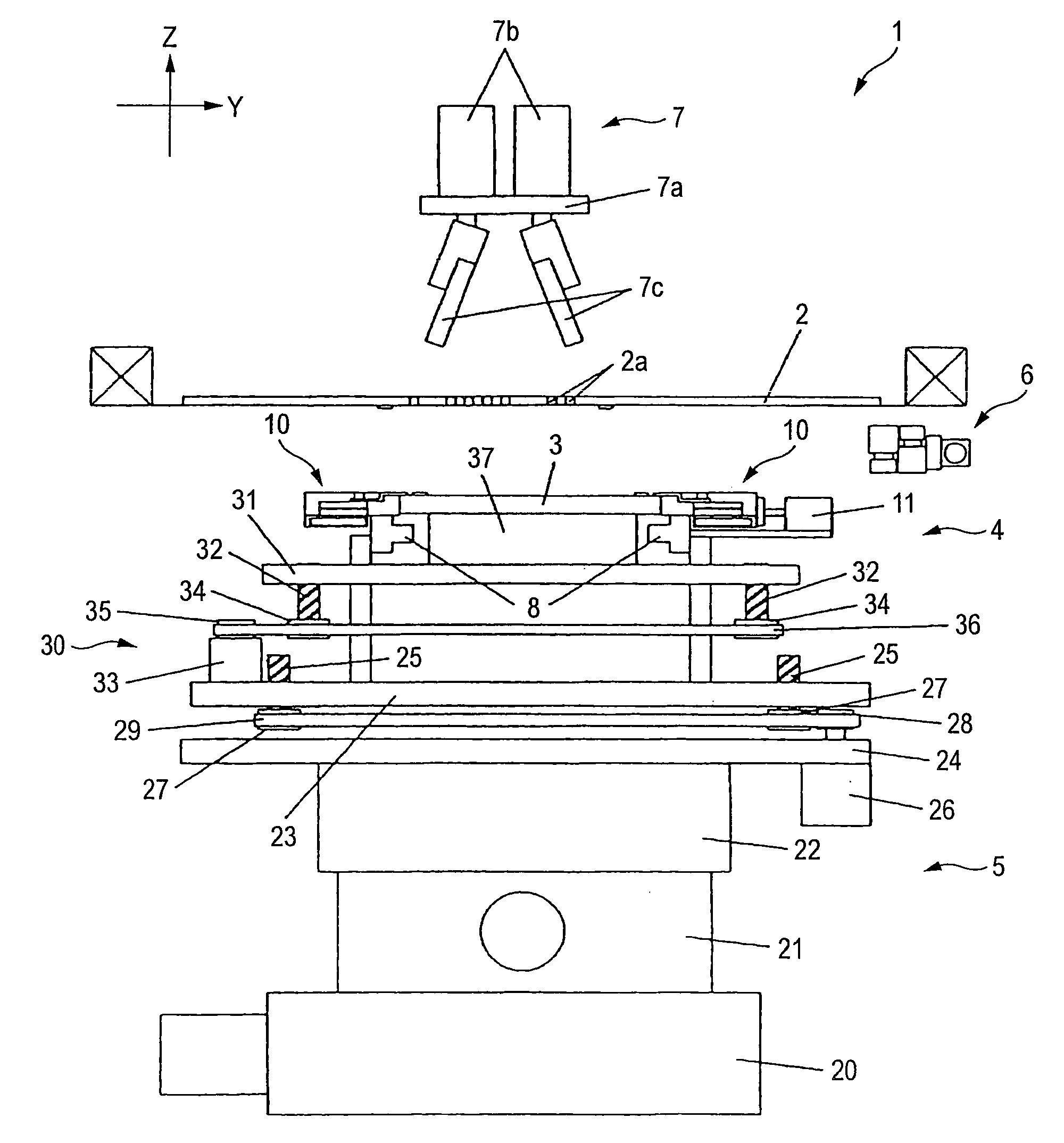
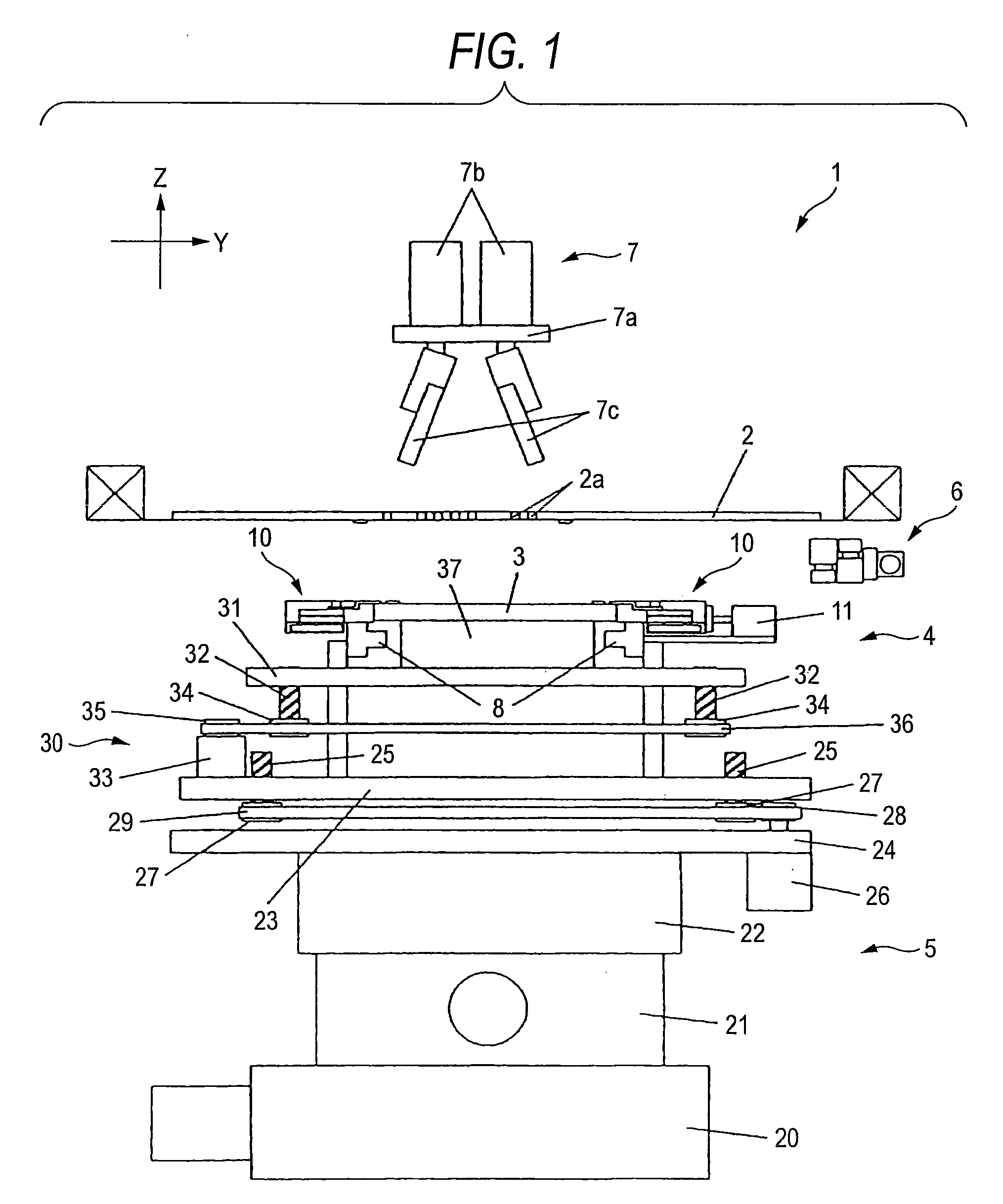
[0039]One embodiment of the invention will be described with reference to the accompanying drawings. FIG. 1 is a side view of a screen printing apparatus according to one embodiment of the invention, FIG. 2 is a front view of the screen printing apparatus according to one embodiment of the invention, FIG. 3A is a plan view of a substrate supporter according to one embodiment of the invention, FIG. 3B is a plan view of the substrate supporter according to one embodiment of the invention, FIG. 4A is a partial side sectional view of the substrate supporter according to one embodiment of the invention, FIG. 4B is a partial side sectional view of the substrate supporter according to one embodiment of the invention, FIG. 4C is a partial side sectional view of the substrate supporter according to one embodiment of the invention, FIG. 5 is a plan view and partially enlarged plan view of the substrate supporter according to one embodiment of the invention, FIG. 6A is an explanatory view of t...


PUM


Abstract

Movable claws 13 are formed in dampers 10 holding a substrate 3 so that the movable claws can be selectively moved to a position where they have projected above the substrate 3, and to a position where they have retreated from above the substrate 3. Thereby, the safety of operation is ensured by causing the movable claws 13 to retreat during maintenance. Moreover, printing with high precision can be performed in a state where the surface of the substrate 3 and the rear face of the mask 2 are brought into surface contact with each other without any clearance by causing the movable claws 13 to retreat.

Description

BACKGROUND OF THE INVENTION[0001]1. Field of the Invention[0002]The present invention relates to a screen printing apparatus and a screen printing method which print a pattern with paste on the surface of a substrate which is aligned with a mask in which predetermined pattern openings are formed.[0003]2. Related Art[0004]In a mounting process of electronic components, screen printing of supplying a pasted conductive material (conductive paste, hereinafter simply referred to as ‘paste’) onto the surface of a substrate is used frequently in order to mechanically and electrically join electronic components to the substrate. The screen printing includes supplying paste onto the surface of a mask provided with pattern openings formed in a predetermined pattern in a state where the mask is brought into surface contact with the surface of a substrate, and applying and spreading the paste on the surface of the mask by means of a squeegee which slides on the surface of the mask, thereby prin...

Claims


Application Information

Patent Timeline
12 Nov 2009
Publication
US20090277348A1
IPC
B41F15/08
CPC
B41F15/22; H05K2203/0165; H05K3/1216; B41P2215/114; B41F15/085; B41F15/16; B41F15/18; B41F15/26
Inventors
ABE, SEIKOU; TOKITA, KUNIHIKO