Pneumatic tire

a technology of pneumatic tires and reinforcing belts, which is applied in the field of pneumatic tires, can solve the problems of easy fatigue of the circumferential-direction reinforcing belt edge portion, and achieve the effects of reducing the risk of fatigue rupture, and increasing the width

Active Publication Date: 2009-11-12
THE YOKOHAMA RUBBER CO LTD
View PDF9 Cites 43 Cited by
  • Summary
  • Abstract
  • Description
  • Claims
  • Application Information

AI Technical Summary

Benefits of technology

[0006]In the present invention, it is possible to inhibit a fatigue rupture at an edge portion of the circumferential-direction reinforcing belt layer by sandwiching the circumferential-direction reinforcing belt layer between the crossed belt layers each of which has a greater width than that of the circumferential-direction reinforcing belt layer. Moreover, by providing the stress relaxation layer outside of the circumferential-direction reinforcing belt layer in the width directions, it is also possible to relax shear strain at edge portions of the crossed belt layers, and thus to inhibit a separation at that portion. Thus, it is possible to inhibit the separation at the edge portions of the crossed belt layers while inhibiting the fatigue rupture at the edge portion of the circumferential-direction reinforcing belt layer, by constructing the belt structure including the crossed belt layers, the circumferential-direction reinforcing belt layer and the stress relaxation layer as described above.
[0007]In the present invention, to effectively relax shear strain at an edge portion of the crossed belt layers, it is preferable that a rubber composition constituting the stress relaxation layer have a smaller modulus at 100% elongation than a modulus at 100% elongation of a rubber composition that covers cords of the crossed belt layers. Particularly, a modulus Ea at 100% elongation of the rubber composition constituting the stress relaxation layer and a modulus Eco at 100% elongation of the rubber composition that covers cords of the crossed belt layers preferably satisfy a relation of 0.6≦Ea / Eco≦0.9. Furthermore, the modulus at 100% elongation of the rubber composition constituting the stress relaxation layer is preferably within a range from 4.0 MPa to 5.5 MPa. Note that, in the present invention, a modulus at 100% elongation is measured in accordance with the measurement method for tensile stress at a predetermined elongation, which is specified by JIS K6251.
[0008]The circumferential-direction reinforcing belt layer preferably has a cord angle of 0 to 5 degrees with respect to a tire circumferential direction, and has a width that is from 60% to 75% of a carcass section width. Each of the crossed belt layers preferably has a cord angle of 10 to 45 degrees with respect to the tire circumferential direction, and has a width greater than that of the circumferential-direction reinforcing belt layer by at least 10% of the carcass section width. By the combination of the circumferential-direction reinforcing belt layer and the crossed belt layers described above, the belt structure can exert its excellent performance.
[0009]In addition to the above-described stress relaxation layer, it is preferable to dispose an edge-portion buffering layer, made of the rubber composition, between the crossed belt layers and at a position corresponding to edge portions of the crossed belt layers. The stress relaxation layer is preferably disposed over an entire region between the circumferential-direction reinforcing belt layer and the edge-portion buffering layer. Meanwhile, an inter-cord rubber gauge t of a portion where the stress relaxation layer is interposed between the crossed belt layers preferably satisfies a relation of 0.8 D≦t≦1.7 D where D represents a cord diameter of the circumferential-direction reinforcing belt layer. Thereby, it is possible to effectively inhibit a separation at edge portions of the crossed belt layers.
[0010]It is preferable to dispose a high-angle belt layer between the carcass layer and the crossed belt layer. The high-angle belt layer preferably has a cord angle of 45 to 90 degrees with respect to the tire circumferential direction, and has a width that is from 60% to 85% of the carcass section width. Such a high-angle belt layer serves to prevent buckling of the tread portion by increasing bending rigidity of the belt structure.
[0011]It is preferable to dispose a protection belt layer on the outer circumferential side of the crossed belt layer. The protection belt layer preferably has a cord angle of 10 to 45 degrees with respect to the tire circumferential direction, and has a width that is from 60 to 85% of the carcass section width. Such a protection belt layer serves to protect the belt structure from damage.

Problems solved by technology

Accordingly, the cords at the edge portion of the circumferential-direction reinforcing belt layer are susceptible to a fatigue rupture.

Method used


Image

  • Pneumatic tire
  • Pneumatic tire
  • Pneumatic tire

Examples


examples

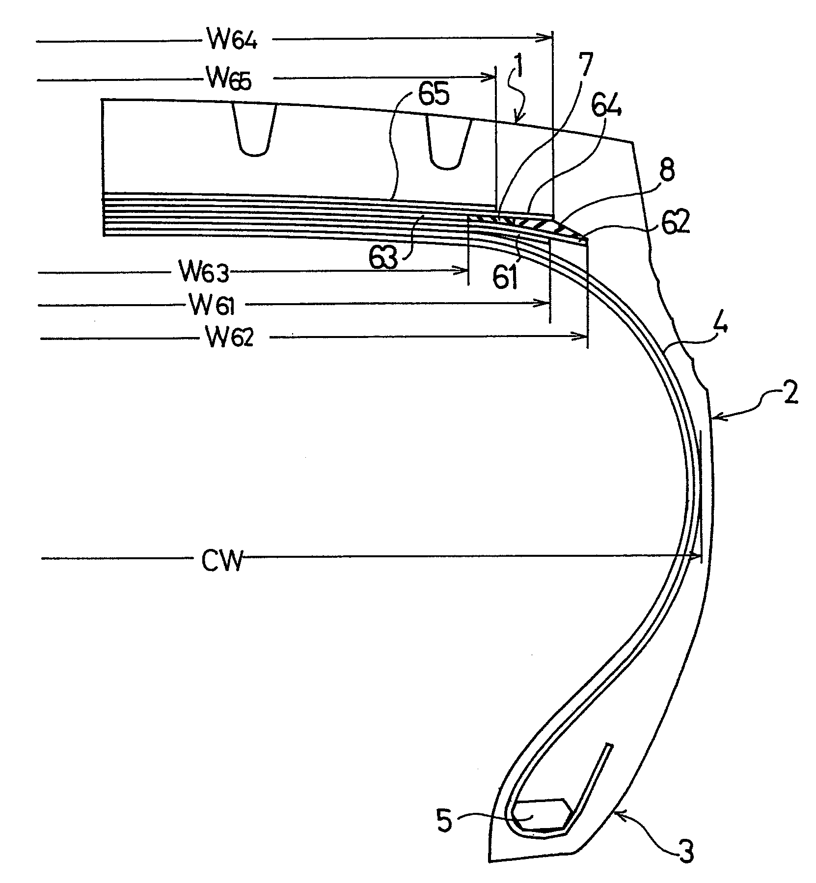
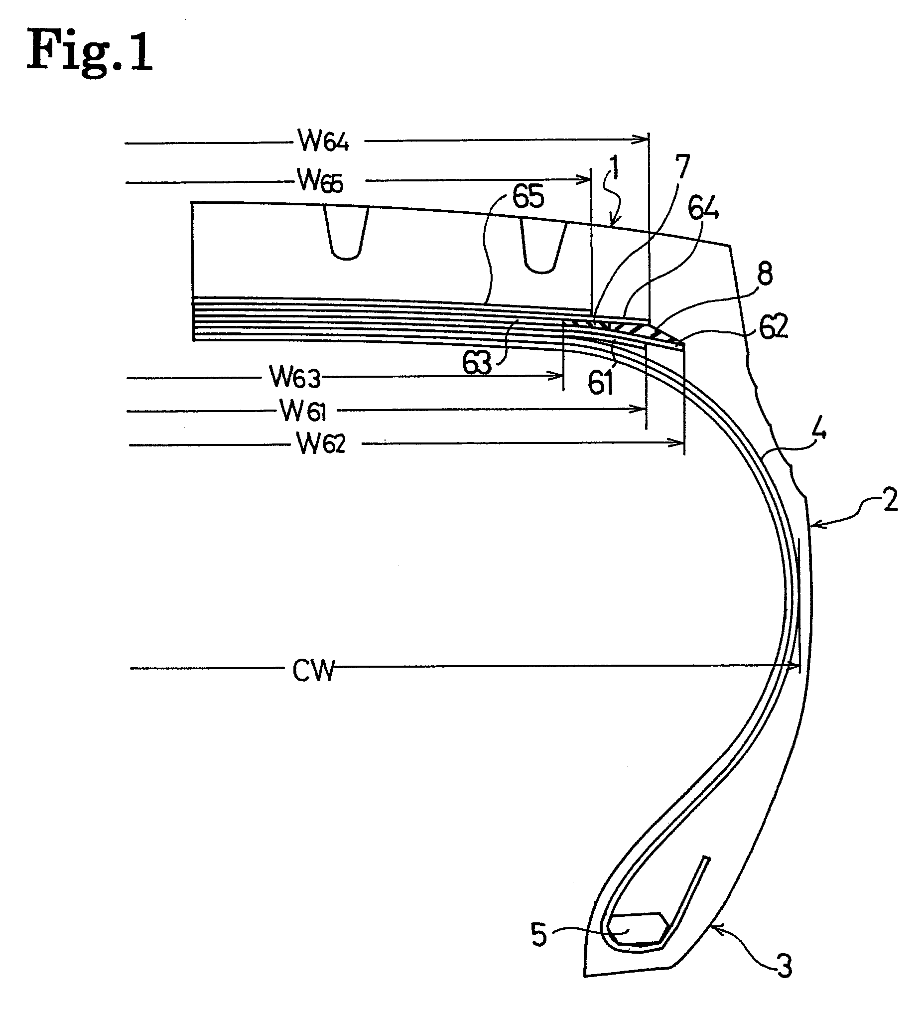
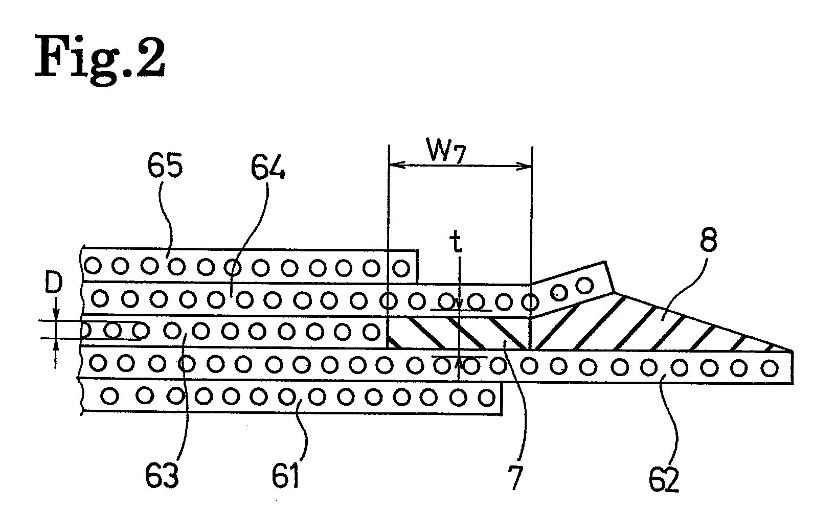
[0040]Tires of Examples 1 and 2 were manufactured each of which was provided with a stress relaxation layer and an edge-portion buffering layer disposed between the crossed belt layers and outside, in width directions, of the circumferential-direction reinforcing belt layer. Each tire had a tire size of 435 / 45R22.5 164J, and a high-angle belt layer (first belt layer), a crossed belt layer (second belt layer), a circumferential-direction reinforcing belt layer (third belt layer), a crossed belt layer (fourth belt layer), and a protection belt layer (fifth belt layer) were disposed on the outer circumferential side of a carcass layer. For comparison, a conventional tire which had the same structure as those in Examples 1 and 2, except that a stress relaxation layer was not provided therein, was prepared. Note that, a modulus at 100% elongation of the rubber composition that covered the cords of all the belt layers was set to 6.3 MPa, and a modulus at 100% elongation of the rubber comp...


PUM


Abstract

The present invention provides a pneumatic tire that inhibits any fatigue rupture at an edge portion of a circumferential-direction reinforcing belt layer and also inhibits any separation at an edge portion of crossed belt layers. In the pneumatic tire, at least two crossed belt layers are disposed on the outer circumferential side of a carcass layer in a tread portion. At least one circumferential-direction reinforcing belt layer with a width smaller than those of the crossed belt layers is disposed between the crossed belt layers. Moreover, a stress relaxation layer of a rubber composition having a fixed thickness is disposed between the crossed belt layers while lying adjacent to an edge portion of and outside, in the width directions of, the circumferential-direction reinforcing belt layer.

Description

TECHNICAL FIELD[0001]The present invention relates to a pneumatic tire suitable for a heavy-duty tire with an aspect ratio of 60% or less. Further specifically, the present invention relates to a pneumatic tire capable of inhibiting a fatigue rupture at an edge portion of a circumferential-direction reinforcing belt layer, and also inhibiting a separation at edge portions of crossed belt layers.BACKGROUND ART[0002]Recently, the aspect ratio of heavy-duty tires used for trucks and buses is now being reduced. Particularly, in many cases of tires with an aspect ratio of 60% or less, a circumferential-direction reinforcing belt layer having a cord angle of substantially 0° to a tire circumferential direction is disposed between crossed belt layers (see, for example, Patent Document 1). In such a belt structure, the cord tension at an edge portion of the circumferential-direction reinforcing belt layer is high. Accordingly, the cords at the edge portion of the circumferential-direction r...

Claims


Application Information

Patent Timeline
Patent Type & Authority Applications(United States)
IPC IPC(8): B60C9/18
CPCB60C9/2006B60C2200/06Y10T152/1081B60C2009/1842B60C9/185B60C2009/1871B60C9/28
Inventor SUZUKI, NOBUOISOBE, SATORUKABE, KAZUYUKI
Owner THE YOKOHAMA RUBBER CO LTD
Why Eureka
Try Eureka