
Transformer core and its manufacturing method

a transformer core and manufacturing method technology, applied in the direction of transformer/inductance magnetic cores, transformer/yokes, inductances, etc., can solve the problems of difficult to remarkably expand the magnetic gap, the operation of applying or injecting pasty adhesives to or into the space, and the inductance of a transformer core may vary remarkably, so as to achieve the effect of reducing the number of drops

Inactive Publication Date: 2009-11-12
HITACHI METALS LTD
View PDF5 Cites 11 Cited by
  • Summary
  • Abstract
  • Description
  • Claims
  • Application Information

AI Technical Summary

Benefits of technology

[0006]The present invention has been proposed in order to solve the aforementioned problems, and an object of the present invention is to provide a transformer core mountable also on a coil whose both ends are connected to a substrate or the like, capable of simplifying a step of providing adhesive layers and capable of inhibiting a magnetic gap from fluctuation and a its manufacturing method.

Problems solved by technology

In a case of forming a magnetic gap in an annular magnetic core, there is such an inconvenience that the inductance of a transformer core may remarkably vary due to change of the magnetic gap during the use of the magnetic core.
In the core case assembly disclosed in the aforementioned Japanese Patent Laying-Open No. 8-17649, however, the core case and the annular core are so annularly formed as to have one magnetic gap, whereby it is difficult to remarkably expand the magnetic gap.
Therefore, there is such a problem that it is difficult to mount the core case assembly disclosed in the aforementioned Japanese Patent Laying-Open No. 8-17649 on a coil whose both ends are connected to a substrate or the like.
Further, the core case assembly disclosed in the aforementioned Japanese Patent Laying-Open No. 8-17649 has such an inconvenience that the operation of applying or injecting the pasty adhesive to or into the space between the spacer body portion and the platelike cover portion and the magnetic gap and the peripheral portion thereof and solidifying (curing) the same is complicated and requires time.
Therefore, there is such a problem that it is difficult to simplify a step of providing an adhesive layer.

Method used


Image

  • Transformer core and its manufacturing method
  • Transformer core and its manufacturing method
  • Transformer core and its manufacturing method

Examples


first embodiment

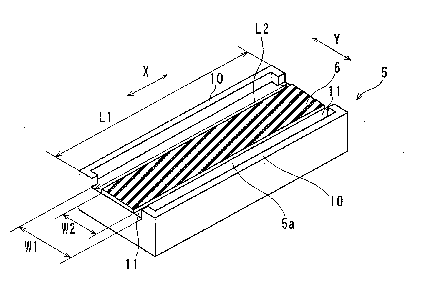
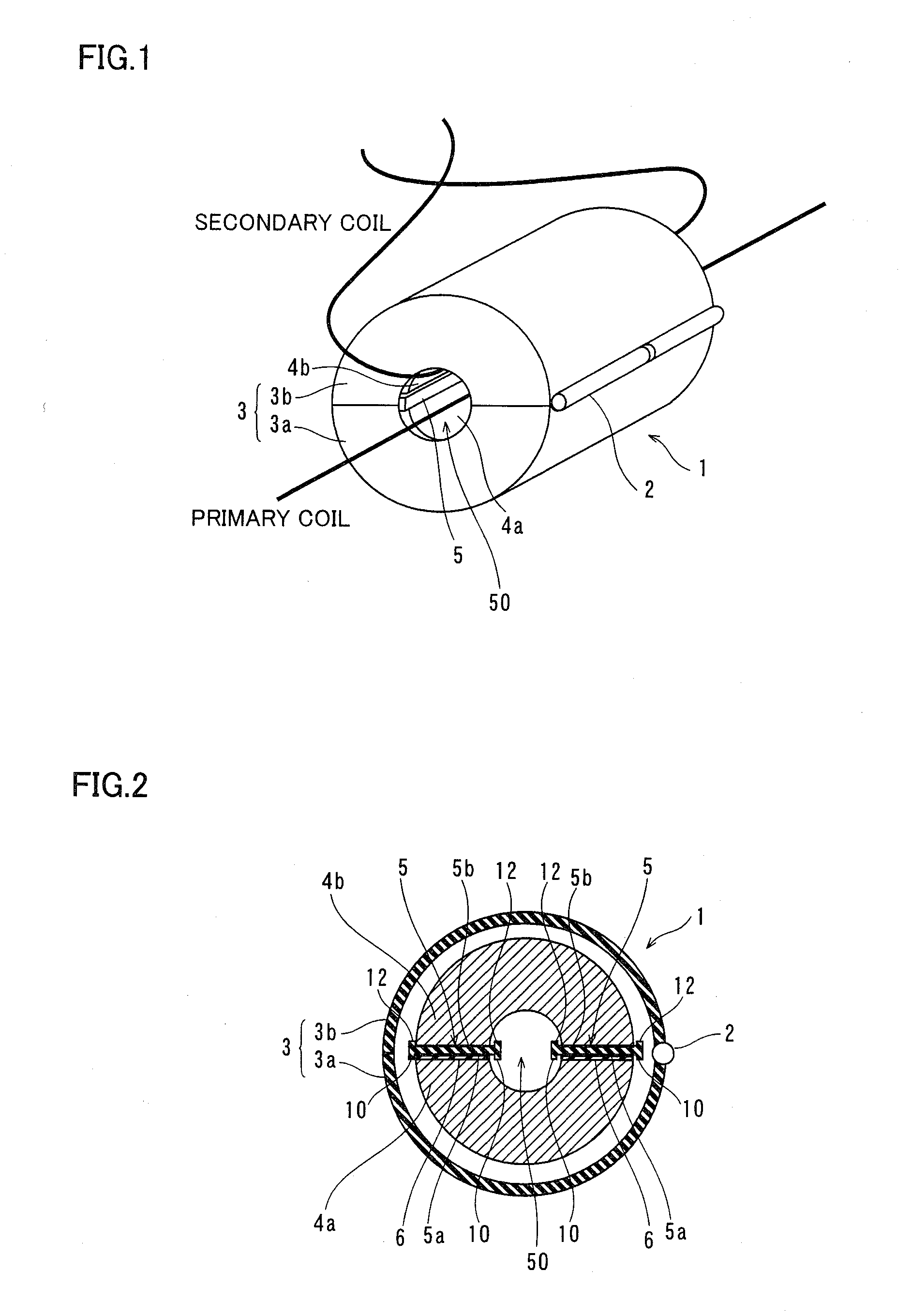
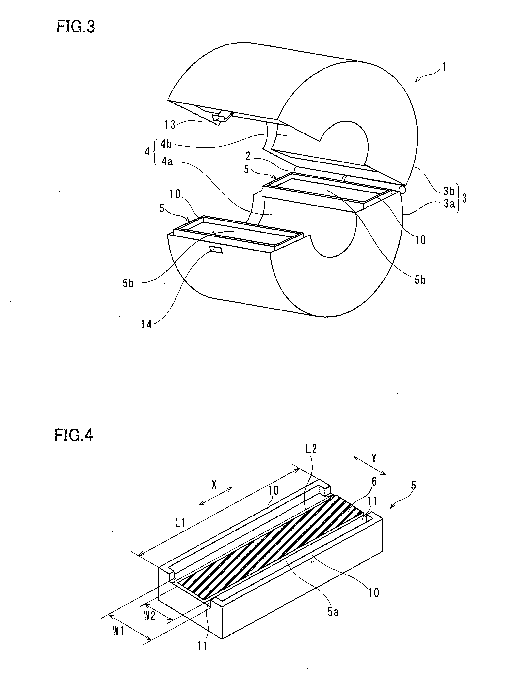
[0044]First, the structure of a transformer core 1 according to a first embodiment is described with reference to FIGS. 1 to 6.

[0045]According to the first embodiment, the transformer core 1 is constituted of a clamp mechanism 2, a core case 3, a soft ferrite core 4, spacers 5 and sheet-shaped adhesive layers 6 formed by double-faced adhesive tapes substantially unchanging in thickness, as shown in FIGS. 1 to 3.

[0046]More specifically, the core case 3 is formed by a pair of a first core case 3a and a second core case 3b having semicircular outer peripheral surfaces, and the first core case 3a and the second core case 3b are coupled with each other through the clamp mechanism 2. As shown in FIG. 3, the first core case 3a has a pawl 13, while the second core case 3b has an engaging hole 14 engageable with the pawl 13 of the first core case 3a. With this pawl 13 and the engaging hole 14, the first core case 3a and the second core case 3b are so formed as to keep a closed state in a sta...

second embodiment

[0068]Referring to FIGS. 9 to 11, this second embodiment is described with reference to a case of employing a spacer provided with regions not provided with convex portions on parts of the respective ones of a pair of opposing sides of convex portions of a first surface and the remaining pair of opposing sides, dissimilarly to the aforementioned first embodiment.

[0069]According to this embodiment, convex portions 21 are integrally provided on four sides of a first surface 20a of a spacer 20, as shown in FIGS. 9 and 11. Further, regions 22 and 23 not provided with the convex portions 21 are provided on a pair of opposing sides and the remaining pair of opposing sides respectively, and the convex portions 21 are formed on the four corners of the first surface 20a of the spacer 20. The convex portions 21 are examples of the “first convex portions” in the present invention.

[0070]On four sides of a second surface 20b of the spacer 20, convex portions 24 are integrally provided on all reg...


PUM

PropertyMeasurementUnit
magnetic gapaaaaaaaaaa
widthaaaaaaaaaa
magneticaaaaaaaaaa

Abstract

It is possible to provide a transformer core which can be mounted on a coil having both ends connected to a substrate or the like and can simplify the step for arranging an adhesive layer and suppress fluctuation of a magnetic gap. The transformer core (1) includes: a rectangular spacer (5, 20) having a region where a first convex portion (10, 21) is formed on the four sides of one of the surfaces as a unitary block and the first convex portion is not provided at least at a part of a pair of two opposing sides; and a sheet-shaped adhesive layer (6) bonded to a region where at least the first convex portion is not provided on the one of the surfaces of the spacer and connecting a soft ferrite core (4) to the spacer.

Description

TECHNICAL FIELD[0001]The present invention relates to a transformer core and its manufacturing method, and more particularly, it relates to a transformer core whose ferrite core has a magnetic gap and its manufacturing method.BACKGROUND ART[0002]In relation to a transformer core used under such a condition that a direct current is superimposed on a coil, a technique of providing a magnetic gap serving as a space (clearance) on a part of a magnetic path in order to prevent magnetic saturation of the core is widely known in general. In this case, a soft ferrite core of Mn—Zn, Ni—Zn and so on is used as a magnetic core.[0003]In a case of forming a magnetic gap in an annular magnetic core, there is such an inconvenience that the inductance of a transformer core may remarkably vary due to change of the magnetic gap during the use of the magnetic core. The magnetic gap fluctuates due to the working environment (temperature change, humidity change, pressure change, vibration, weather resis...

Claims


Application Information

Patent Timeline
Patent Type & Authority Applications(United States)
IPC IPC(8): B32B37/16H01F27/24
CPCH01F2017/065H01F3/14
Inventor UEMURA, MASAYASU
Owner HITACHI METALS LTD
Learn More