Heat dissipating device and heat conduction structure thereof

a heat dissipating device and heat conduction technology, which is applied in the direction of basic electric elements, semiconductor devices, lighting and heating apparatus, etc., can solve the problems of heat conduction structure dissipation, and achieve the best improve the heat dissipation efficiency of the heat dissipation device

Inactive Publication Date: 2009-11-12
CHAUN CHOUNG TECH
View PDF9 Cites 18 Cited by
  • Summary
  • Abstract
  • Description
  • Claims
  • Application Information

AI Technical Summary

Benefits of technology

[0010]The present invention relates to a heat dissipating device. At least one heat pipe is disposed in the receiving space and sandwiched between the first heat conduction plate and the second heat conduction plate. The number of the at least one heat pipe can be configured to increase or reduce depending on the heat area size of the heat generating element. A best heat dissipating efficiency of the heat dissipating device can be achieved.
[0011]The present invention also relates to a heat dissipating device. The heat emitting sections are disposed in the heat dissipating passages. The airflow from the fan can flow through the heat dissipating passages to improve the heat dissipating efficiency of the heat dissipating device.

Problems solved by technology

Therefore, the heat conduction structure may dissipate heat by outer winds blowing to the heat emitting sections.

Method used


Image

  • Heat dissipating device and heat conduction structure thereof
  • Heat dissipating device and heat conduction structure thereof
  • Heat dissipating device and heat conduction structure thereof

Examples


first embodiment

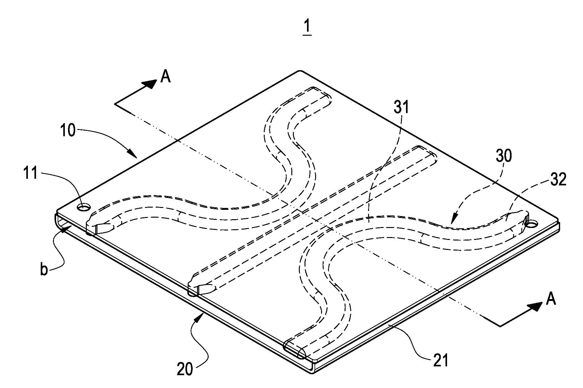
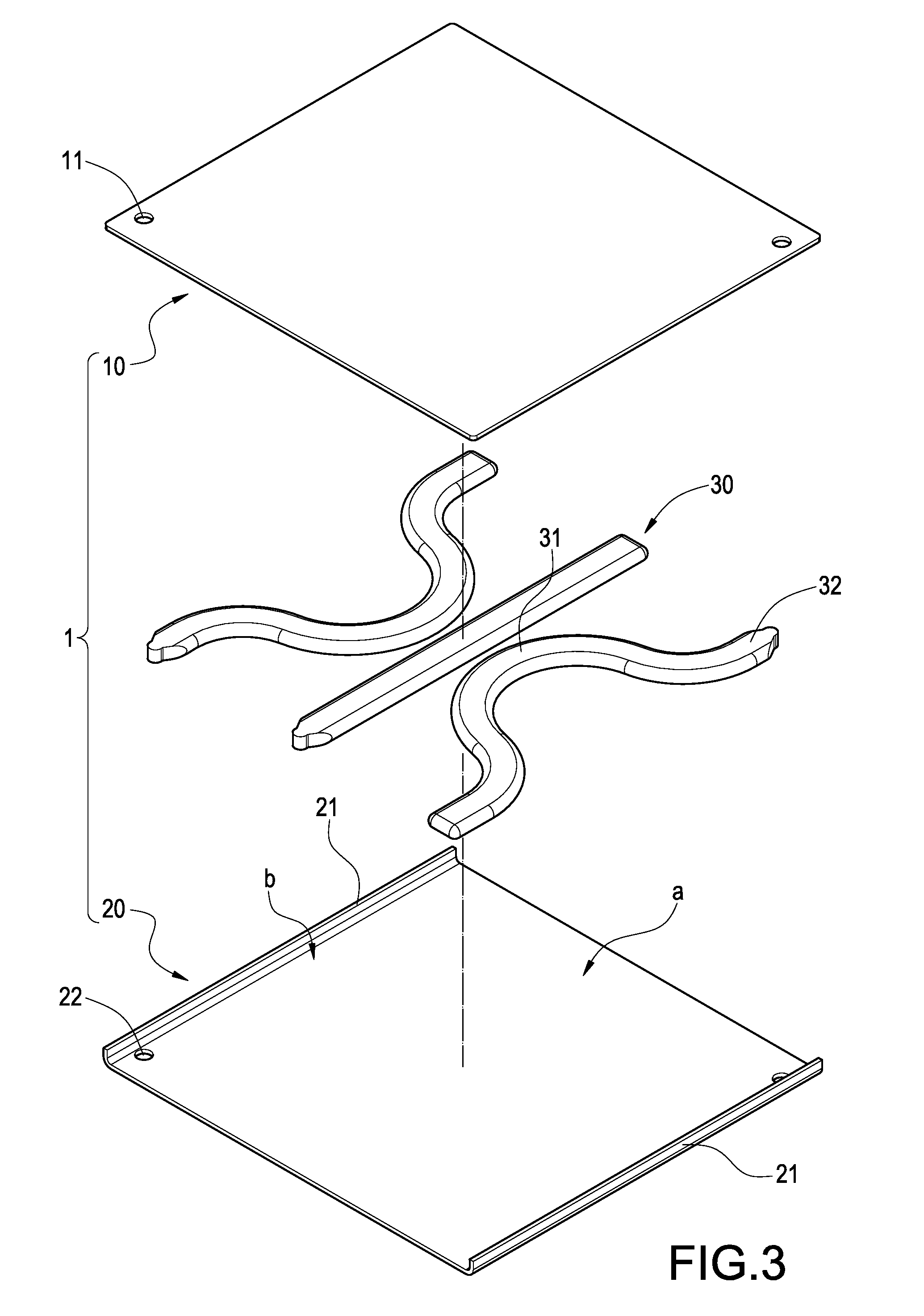
[0027]At least three heat pipes 30 are used in the present invention. The heat pipes 30 are arranged in the receiving space “a”, and sandwiched between the first heat conduction plate 10 and the second heat conduction plate 20. Each heat pipe 30 includes a heat absorbing section 31 and a heat emitting section 32 extending from each heat absorbing section 31. A plurality of heat dissipating passages “b” is formed between the heat emitting sections 32 and the walls 21. Each heat emitting section 32 is partially positioned in the heat dissipating passages “b”. Each heat pipe 30 has a tabular configuration.

[0028]Referring also to FIG. 6 to FIG. 7, an exploded view of a heat dissipating device of the present invention, and a lateral sectional view of the first embodiment of the present invention are shown. The heat dissipating device further includes a heat dissipating body 40 and a fan 50 (shown in FIG. 10). The heat dissipating body 40 is attached to the surface of the first heat condu...

third embodiment

[0032]Referring to FIG. 10, a top sectional view of the present invention is shown. This heat dissipating device includes a fan 50 disposed at a lateral side of the heat conduction structure 1 and connected thereto. The airflow generated from the fan 50 flows into the heat dissipating passage “b” to dissipate heat from the heat emitting sections 32 of the heat pipes 30. Therefore, the heat conducting efficiency of the heat conduction structure is improved. The whole heat dissipating device can be dissipated. The heat dissipating device can produce the best heat dissipating efficiency.

[0033]The heat dissipating device and the heat conduction structure of present invention has the following advantages: First, the heat pipes 30 are sandwiched between the first heat conduction plate 10 and the second heat conduction plate 20. The arrangement of the heat pipes 30 can be configured by the size of the heat generating element 61. Therefore, the heat dissipating device and the heat conductio...


PUM


Abstract

The heat conduction structure includes a first heat conduction plate, a second heat conduction plate and at least one heat pipes. The second heat conduction plate is positioned below the first heat conduction plate. A pair of walls extends from two opposite edges of the second heat conduction plate. The walls connect to a bottom surface of the first heat conduction plate. A receiving space is defined between the first heat conduction plate and the second heat conduction plate. At least one heat pipe is arranged in the receiving space and sandwiched between the first heat conduction plate and the second heat conduction plate. Each heat pipe has a heat absorbing section and a plurality of heat emitting sections extending from each heat absorbing section. A plurality of heat dissipating passages is defined between the at least one heat pipe and the walls. The heat emitting sections are partially positioned in the heat dissipating passages. The heat conduction structure can combine with a heat dissipating body and a fan to a heat dissipating device.

Description

BACKGROUND[0001]The present invention relates to a heat conduction structure, especially to a heat dissipating device with heat dissipating passages and the heat conduction structure thereof.[0002]Generally, a heat dissipating device is attached to a heat generating elements with direct contact, and a contact surface of the heat dissipating device is always made of metal with good thermal conductivity. Heat can be rapidly conducted from a heat generating element to the fins of the heat dissipating device.[0003]Recently, with the development of the computer, the operating speed of the elements inside the computer is greatly improved, and the heat from per unit area is greatly enhanced accordingly. The metal for thermal conduction is less used due to its insufficient thermal efficiency.[0004]A heat pipe and a vapor chamber are developed afterwards. However, the heat pipe can only provide thermal conduction by a manner of linear contact. The vapor chamber can provide thermal conduction...

Claims


Application Information

Patent Timeline
Patent Type & Authority Applications(United States)
IPC IPC(8): F28D15/00
CPCF28D15/0233F28D15/0275F28F3/02H01L23/427H01L2924/0002H01L2924/00
Inventor LIN, SHIH-YUANWU, CHIEN-HSINGLIN, CHIA-HSUNHSU, SHEN-HUANG
Owner CHAUN CHOUNG TECH
Why Eureka
Try Eureka