Speaker device

a speaker device and speaker technology, applied in the direction of stereophonic arrangments, transducer details, electrical transducers, etc., can solve the problems of inability to perform natural movie reproduction, inability to involve a plurality of people at once in natural movie appreciation, and inability to achieve the natural movie appreciation of movies. natural, large-scale sound pressure reproduction, excellent effect of expanding listening position rang

Inactive Publication Date: 2009-11-12
PANASONIC CORP
View PDF13 Cites 23 Cited by
  • Summary
  • Abstract
  • Description
  • Claims
  • Application Information

AI Technical Summary

Benefits of technology

[0027]With the speaker device of the foregoing configuration, a sound pressure arriving from the speaker system closer to the listening position can be decreased significantly in the entire band in the mid-range and above, as compared with a sound pressure arriving from the speaker system farther from the listening position, by utilizing the directivity of the first speaker unit with respect to the treble range, and by utilizing the phase difference between emitted sounds of the first and second speaker units and the arrangement position relationship with respect to the mid-range. Therefore, it is possible to achieve an excellent

Problems solved by technology

In the case where center channel signals are reproduced by right and left speakers as described above, if the listening position is deviated from the midmost area, sound images of voice such as speech on the center channel are localized at positions extremely deviated from the screen center, which causes a listener to feel sense of discomfort.
Thus, natural reproduction of movies cannot be performed.
Therefore, with the method in which no independent center speaker is installed, it is impossible for a plurality of persons to be involved at once in natural appreciation of movies.
Likewise, in the stereo music reproduction also, it is impossible for a plur

Method used


Image

  • Speaker device
  • Speaker device
  • Speaker device

Examples


embodiment 1

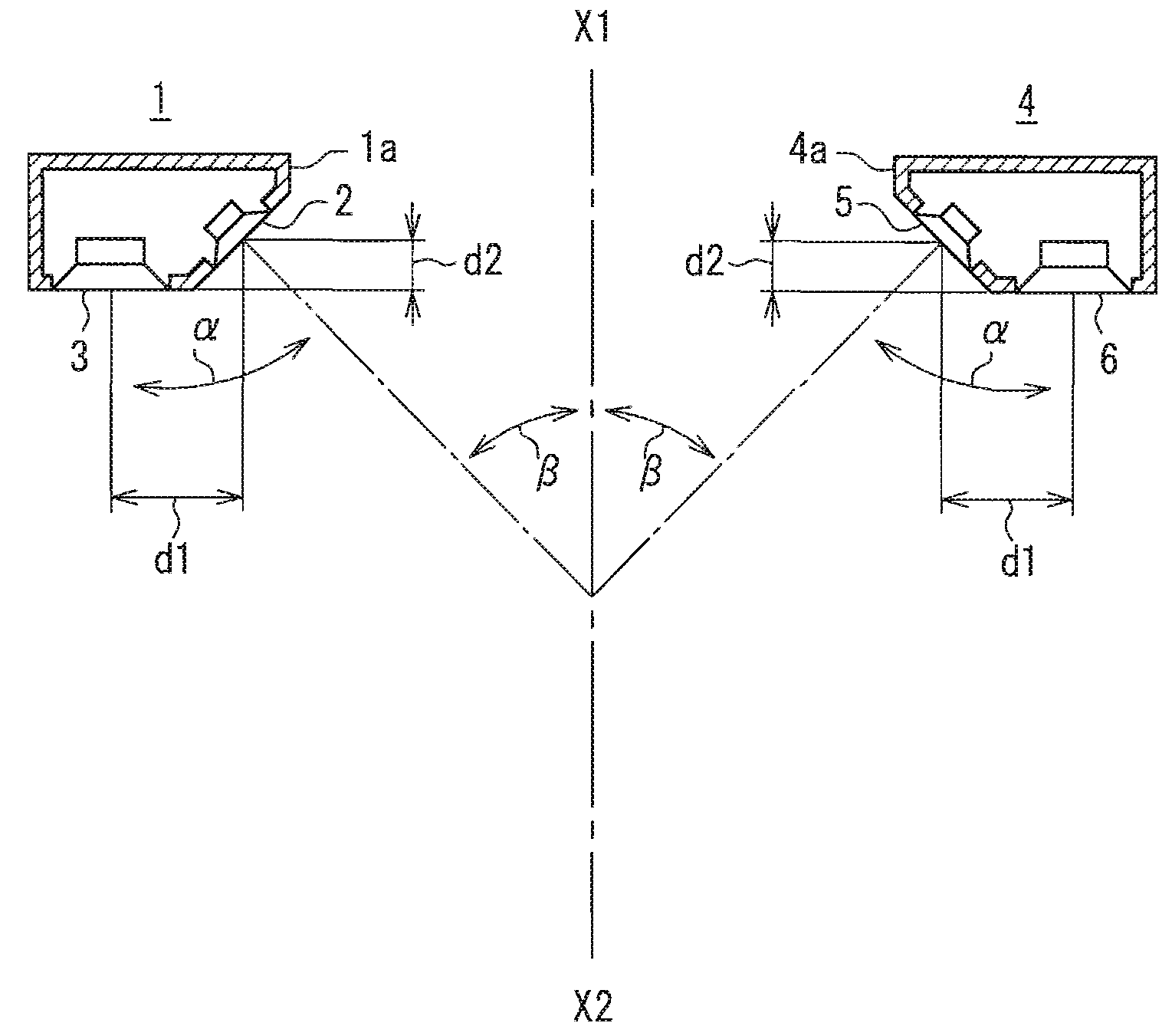
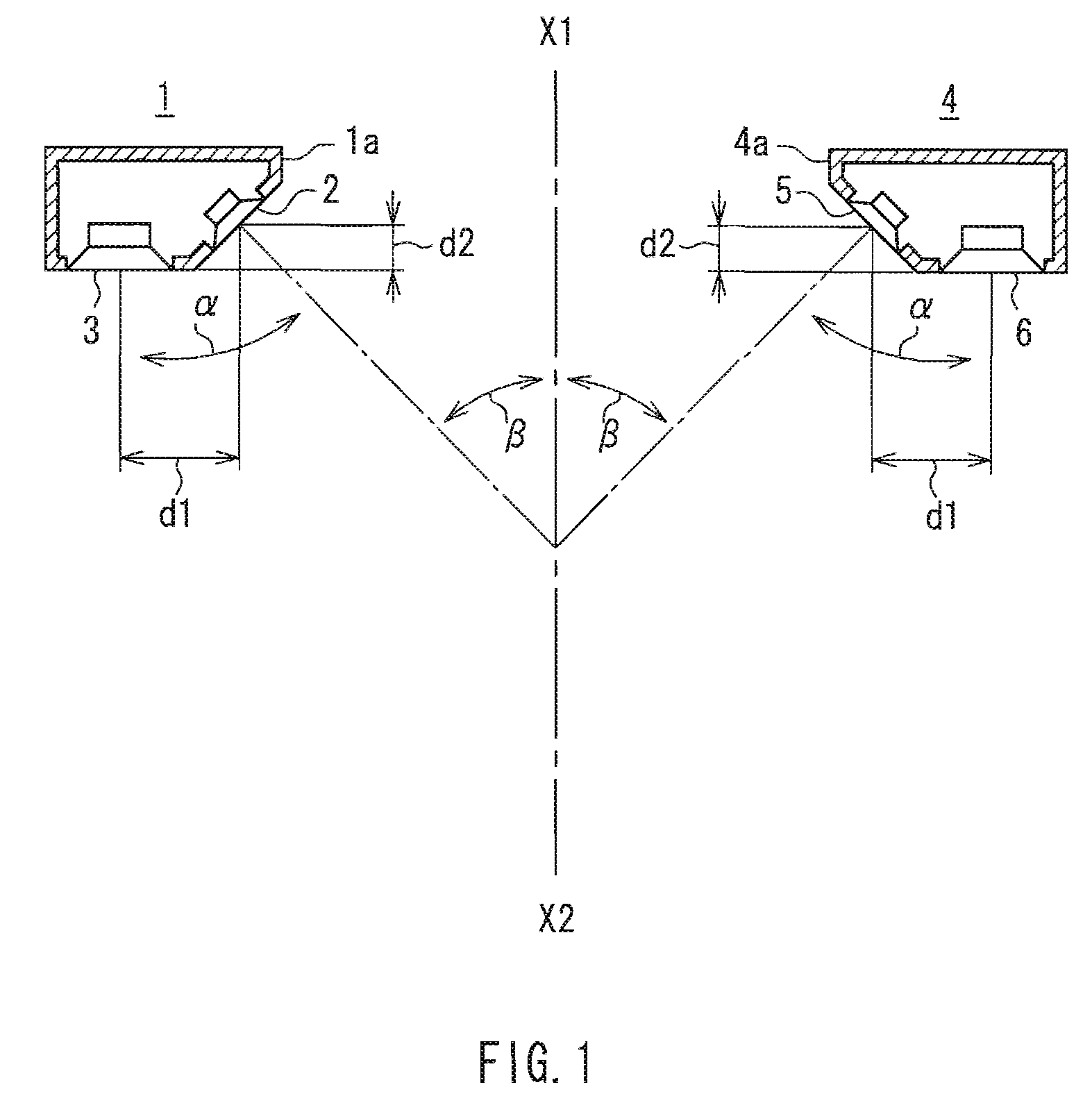
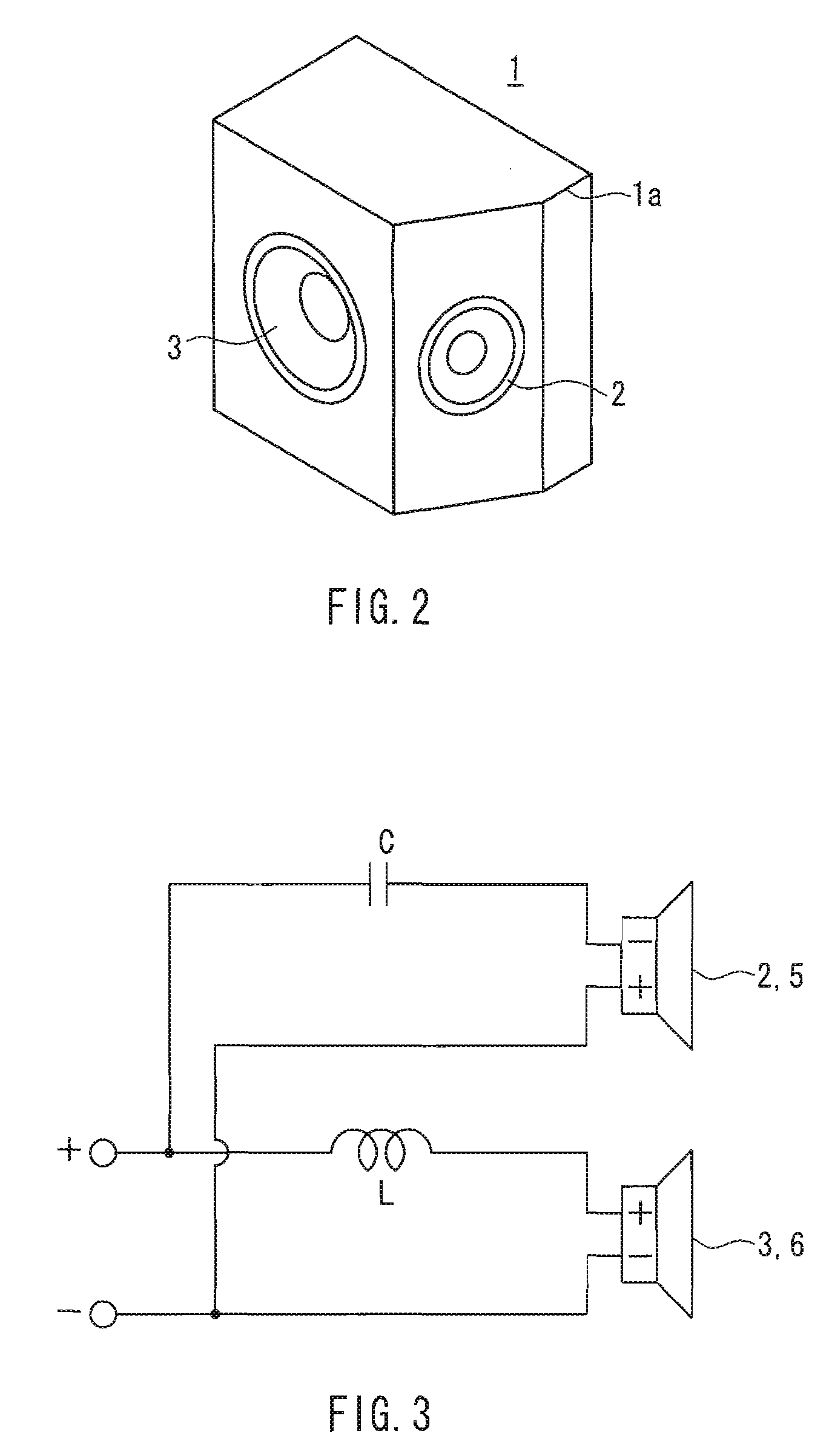
[0082]First of all, a configuration of a speaker device according to Embodiment 1 of the present invention is described below, with reference to FIGS. 1 to 4. FIG. 1 shows a configuration of a speaker device according to Embodiment 1 of the present invention. FIG. 2 is a perspective view of the forgoing speaker device. FIG. 3 is a network circuit diagram of the foregoing speaker device. FIG. 4 is a frequency characteristic diagram of each speaker unit of the foregoing speaker device.

[0083]In FIG. 1, the left-side speaker system 1 and the right-side speaker system 4 are placed on both sides of a listening center axis X1-X2, at substantially the same distances from the listening center axis X1-X2. In a cabinet 1a of the left-side speaker system 1, there are installed a first speaker unit 2 and a second speaker unit 3. In a cabinet 4a of the right-side speaker system 4, there are installed a first speaker unit 5 and a second speaker unit 6. The arrangement of the speaker units 2, 3, 5,...

embodiment 2

[0159]FIG. 11 is a network circuit diagram of a speaker device according to Embodiment 2 of the present invention. FIG. 12 is a frequency characteristic diagram of each speaker unit of the speaker device according to Embodiment 2 of the present invention. In the present embodiment, a cabinet of the speaker system and specifications and arrangement of the speaker units 2, 3, 5, and 6 are similar to those of Embodiment 1.

[0160]Embodiment 2 is different from Embodiment 1 in that the first speaker units 2 and 5 are not sealed on the back and reproduce bass-range sounds, and are also different in the polarities of the first speaker units 2 and 5 and the network circuit configuration.

[0161]As shown in FIG. 11, the treble range of the second speaker units 3 and 6 is attenuated by a 6-dB / oct-type network circuit composed of a treble-cutting coil L1. This point is similar to that of Embodiment 1, but in the present embodiment, a network circuit for each of the first speaker units 2 and 5 is ...

embodiment 3

[0167]FIG. 13 is a speaker unit arrangement diagram of a speaker device according to Embodiment 3 of the present invention. FIG. 14 is a network circuit diagram of the foregoing speaker device. FIG. 15 is a frequency characteristic diagram of each speaker unit of the speaker device. In FIG. 13, first speaker units 12 and 15, second speaker units 13 and 16, and a display 17 are similar to those of Embodiment 1, respectively; therefore, descriptions of the same are omitted herein.

[0168]Embodiment 3 is different from Embodiment 1 in the each shape of speaker systems 11 and 14, i.e., the each shape of cabinets 11a and 14a, the arrangement relationship of the speaker units 12, 13, 15, and 16, and polarities of the first speaker units 12 and 15. The first speaker units 12 and 15 are sealed on the back as in Embodiment 1.

[0169]The first speaker units 12 and 15 are arranged on outer sides with respect to the second speaker units 13 and 16, respectively, and are arranged so as to emit sounds...


PUM


Abstract

A speaker device includes first speaker units 2 and 5 and second speaker units 3 and 6 that are arranged symmetrically as viewed from a listening center axis X1-X2. The first speaker units 2 and 5 emit sounds in inward directions and reproduces at least the mid-range and above, and the second speaker units 3 and 6 emit sounds in a front direction and attenuates the treble range. With respect to a listening position in a front direction of one of the speaker systems 1 and 4, a sound arriving to the listening position from the first speaker unit of the speaker system located closer to the listening position, and a sound arriving thereto from the second speaker unit of the same speaker system, are destructive to each other in the mid-range due to a phase difference, whereby a sound pressure in the mid-range arriving from the speaker system located closer to the listening position is attenuated more, as compared with a sound pressure in the mid-range arriving from the speaker system located farther from the listening position. It is possible to achieve an excellent effect of expanding a listening position range for obtaining the center sound image localization, the natural sound quality without sense of discomfort, the large sound pressure reproduction, and the downsizing.

Description

TECHNICAL FIELD[0001]The present invention relates to a speaker device for use in a movie multichannel sound reproduction equipment such as a stereophonic reproduction equipment or a so-called home theater system.BACKGROUND ART[0002]Generally, in order to achieve excellent sound image localization in stereophonic reproduction, the listening position has to be at the midmost position between fight and left speakers. In other words, if the listening position is deviated from the midmost, closer to one of the speakers, reproduced sound such as a singing voice or another sound that should be heard from the vicinity of the midpoint between the fight and left speakers is heard from the speaker closer to the listening position, whereby sound images are biased toward the speaker closer to the listening position. This is well known.[0003]Further, in order to reproduce movie multichannel in a so-called home theater system, a method is available in which a center channel signal is reproduced b...

Claims


Application Information

Patent Timeline
IPC IPC(8): H04R5/02
CPCH04R5/02
Inventor TANAKA, SHOJI
Owner PANASONIC CORP
Why Eureka
Try Eureka