Image compression apparatus, image expansion apparatus, and image processing apparatus

a compression apparatus and image technology, applied in the direction of electrical devices, instruments, computing, etc., can solve the problems of low compression ratio, large code quantity consumed, and loss of decompression

Inactive Publication Date: 2009-11-12
KK TOSHIBA
View PDF7 Cites 64 Cited by
  • Summary
  • Abstract
  • Description
  • Claims
  • Application Information

AI Technical Summary

Problems solved by technology

However, since the numerical loss level is in units of regions, each of which is composed a plurality of pixels, in the case of Japanese Patent No. 3749752, the compression ratio is low and a large code quantity is consumed due to encoding settings near lossless compression for a partial large brightness variation within a region with less frequent brightness variation (since prediction error is small in this region, the region is switched and set to lossless compression having a low compression ratio and a high degree of decompressibility).
On the other hand, a decompression loss occurs and, therefore, a visual image degradation takes place due to irreversible encoding settings for a partial small brightness variation within a region with more frequent brightness variation (since prediction error is large in this region, the region is switched and set to lossy compression having a high compression ratio).
In addition, encoding of loss level information on those regions is required on a region-by-region basis, thus causing a degradation in encoding efficiency.
This necessity causes an increase in a circuit scale and a decrease in processing speed.

Method used


Image

  • Image compression apparatus, image expansion apparatus, and image processing apparatus
  • Image compression apparatus, image expansion apparatus, and image processing apparatus
  • Image compression apparatus, image expansion apparatus, and image processing apparatus

Examples


first embodiment

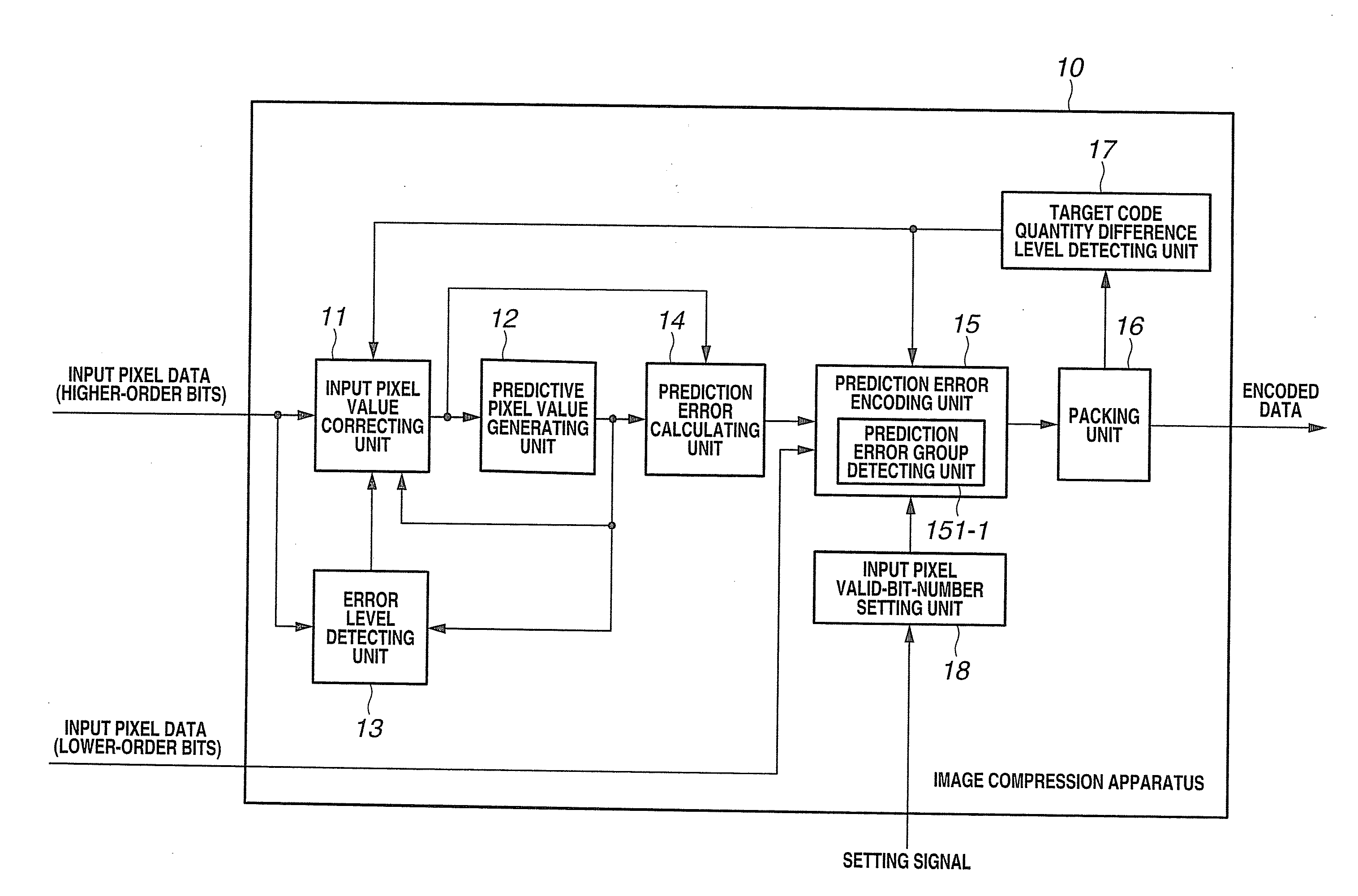
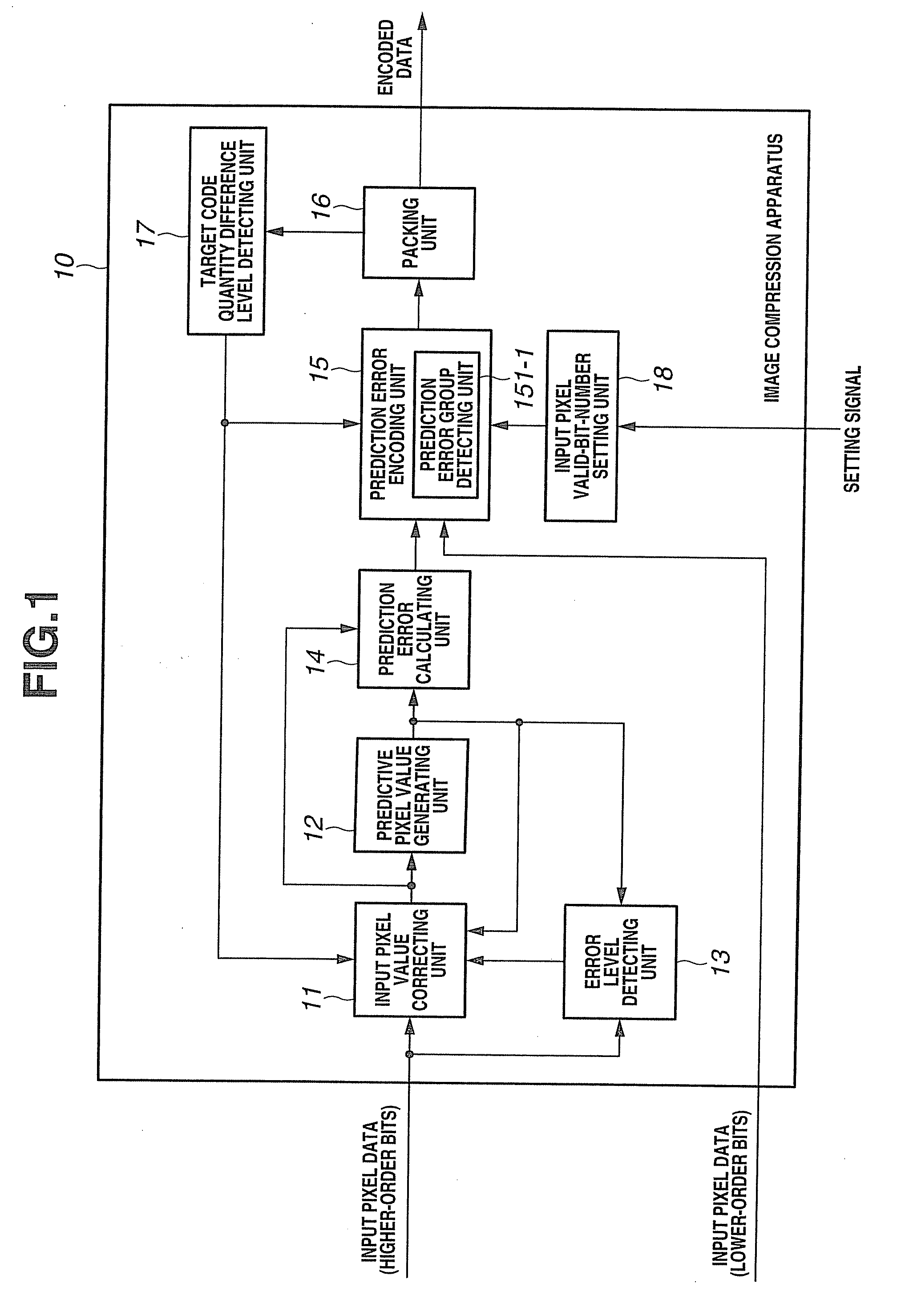
[0040]FIG. 1 is a block diagram showing an image compression apparatus of a first embodiment of the present invention.

[0041]An image compression apparatus 10 shown in FIG. 1 includes: an input pixel valid-bit-number setting unit 18; a predictive pixel value generating unit 12; an error level detecting unit 13; a target code quantity difference level detecting unit 17; an input pixel value correcting unit 11; a prediction error calculating unit 14; a prediction error encoding unit 15; and a packing unit 16.

[0042]The input pixel valid-bit-number setting unit 18 is used to set the input pixel valid-bit-number which is the number of gradations (number of pixel bits) of input pixel data.

[0043]If the input pixel data is made settable to either 10 bits or 8 bits, the encoding operation of the prediction error encoding unit 15 is changed (switched) and set by a one-bit setting signal (signal used to set the data as 10-bit or 8-bit data) input from unillustrated control means, depending on w...

second embodiment

[0108]FIG. 7 is a block diagram showing an image expansion apparatus of a second embodiment of the present invention.

[0109]An image expansion apparatus 20 shown in FIG. 7 includes: an encoded data loading unit 21; a target code quantity difference level detecting unit 25; a prediction error decoding unit 22; a predictive pixel value generating unit 24; and an output pixel valid-bit-number setting unit 26.

[0110]The encoded data loading unit 21 loads encoded data sent from the image compression apparatus of the first embodiment. The target code quantity difference level detecting unit 25 detects a target code quantity difference level indicative of a magnitude by which a code quantity consumed for the number of already-decoded pixels exceeds a target code quantity corresponding to the number of pixels.

[0111]The prediction error decoding unit 22 decodes group information on a prediction error group indicative of the magnitude range of a prediction error of higher-order bits, overhead b...

third embodiment

[0145]FIG. 12 is a block diagram showing an image compression apparatus of a third embodiment of the present invention. Components having the same functions as those shown in the configuration of FIG. 1 in the first embodiment are denoted by like reference numerals in the description to be made hereinafter.

[0146]An image compression apparatus 10C shown in FIG. 12 includes: an input pixel value correcting unit 11A; a predictive pixel value generating unit 12; an error level detecting unit 13; a prediction error calculating unit 14; a prediction error encoding unit 15; a packing unit 16A; a target code quantity difference level detecting unit 17; a correcting data storing unit 19; and an input pixel valid-bit-number setting unit 18.

[0147]The input pixel value correcting unit 11A has the function to replace (correct) lower-order bit data within the higher-order bits of input pixel data, according to an error level between an input pixel value and a predictive pixel value and a target c...


PUM


Abstract

An input pixel valid-bit-number setting unit sets an input pixel valid-bit-number which is the number of gradations of input pixel data. A predictive pixel value generating unit refers to the higher-order bits of earlier already-input pixel data to generate a predictive pixel value for the higher-order bits of a new input pixel. A prediction error group detecting unit detects a prediction error group indicative of the magnitude range of a difference between the predictive pixel value and the value of the higher-order bits of the new input pixel. A prediction error encoding unit multiplexes variable-length encoded information indicative of the prediction error group, overhead bits indicative of a specific value within the prediction error group, and the lower-order bits of the input pixel appropriate for the input pixel valid-bit-number.

Description

CROSS-REFERENCE TO RELATED APPLICATIONS[0001]This application is based upon and claims the benefit of priority from the prior Japanese Patent Application No. 2008-123756 filed in Japan on May 9, 2008; the entire contents of which are incorporated herein by reference.BACKGROUND OF THE INVENTION[0002]1. Field of the Invention[0003]The present invention relates to an image compression apparatus, an image expansion apparatus and an image processing apparatus and, more particularly, to an image compression apparatus, an image expansion apparatus and an image processing apparatus capable of encoding images having various numbers of gradations (different numbers of pixel bits) by common encoding means using no more than a predetermined code quantity.[0004]2. Description of the Related Art[0005]Conventionally, differential pulse code modulation (DPCM) has been used that encodes a difference between an input value and a predictive value (referred to as a prediction error) as a method of reve...

Claims


Application Information

Patent Timeline
Patent Type & Authority Applications(United States)
IPC IPC(8): G06K9/36H04N1/41H04N19/103H04N19/126H04N19/134H04N19/137H04N19/147H04N19/189H04N19/196H04N19/423H04N19/50H04N19/85H04N19/90H04N19/91
CPCH04N19/176H04N19/46H04N19/30H04N19/593H04N19/124H04N19/34H04N19/152H04N19/182H04N19/184H04N19/187H04N19/91
Inventor UETANI, YOSHIHARUBUDSABATHON, CHATREE
Owner KK TOSHIBA
Why Eureka
Try Eureka