Method for determining the rotational speed of the main shaft of a transmission, and transmission comprising a device for detecting rotational speed

a transmission and main shaft technology, applied in the direction of process and machine control, instruments, digital computer details, etc., can solve the problems of insufficient solution, increased transmission weight of sensing gears, and increased transmission length and transmission size, so as to reduce the number of components, simplify assembly, and save weight

Inactive Publication Date: 2009-11-12
ZF FRIEDRICHSHAFEN AG
View PDF7 Cites 21 Cited by
  • Summary
  • Abstract
  • Description
  • Claims
  • Application Information

AI Technical Summary

Benefits of technology

[0010]With the method, the rotational speed of the main shaft is not picked up directly on the main shaft, but rather indirectly from known magnitudes of the planetary gear and the rotational speeds of the ring gear and output shaft or planet carrier. This has the advantage that no rotational speed sensor having a long design or even additional rotational speed sensing gear, must be provided on the main shaft to directly pick up the rotational speed. As a result, an increase in the weight, the length and the volume of the transmission is prevented. Furthermore, reliable rotational speed determination is ensured, even if a floatingly mounted main shaft having large axial play is used. The method enables a determination of the rotational speed of the main shaft of the transmission regardless of the shifting state of the planetary gear.
[0019]In a particularly preferred embodiment of the transmission, the signal transmitter on the ring gear-side is configured as one piece with the ring gear and the other signal transmitter is configured as one piece with the output shaft or the planet carrier. For example, the signal transmitter can be embossed into the corresponding planetary gear part. In this way, the number of components is reduced, thus saving weight and simplifying the assembly.
[0020]In order to further simplify the design and assembly of the transmission, in a further preferred embodiment of the transmission, the first and second rotational speed sensors are disposed on a common sensor module. Thus, by attaching the sensor module inside the transmission, both rotational speed sensors can be installed at the same time.

Problems solved by technology

The rotational speed pickup devices, known from the state of the art, for determining the rotational speed of the main shaft of a transmission, have proven themselves, but are disadvantageous to the extent that the signal transmitter or rotational speed sensing gears increase the transmission weight, the transmission length and the transmission size.
This would, however, once again necessitate providing long sensors or sensor holders, which are prone to vibrations and would put reliable determination of the rotational speed at risk.
Furthermore, when it comes to main shafts with floating support and / or large axial play, the state of the art offers no sufficient solution.
Thus it is not guaranteed in transmissions having such a main shaft that the rotational speed can be reliably picked up on the speed sensor.

Method used


Image

  • Method for determining the rotational speed of the main shaft of a transmission, and transmission comprising a device for detecting rotational speed
  • Method for determining the rotational speed of the main shaft of a transmission, and transmission comprising a device for detecting rotational speed
  • Method for determining the rotational speed of the main shaft of a transmission, and transmission comprising a device for detecting rotational speed

Examples


Embodiment Construction

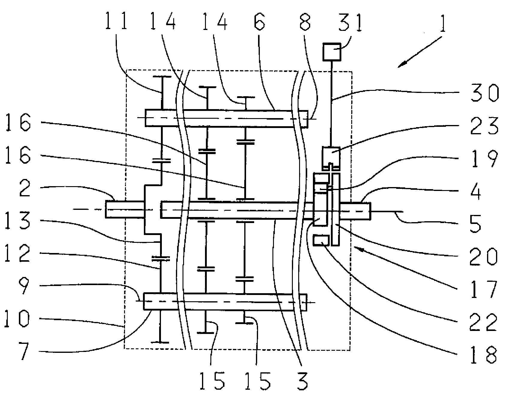
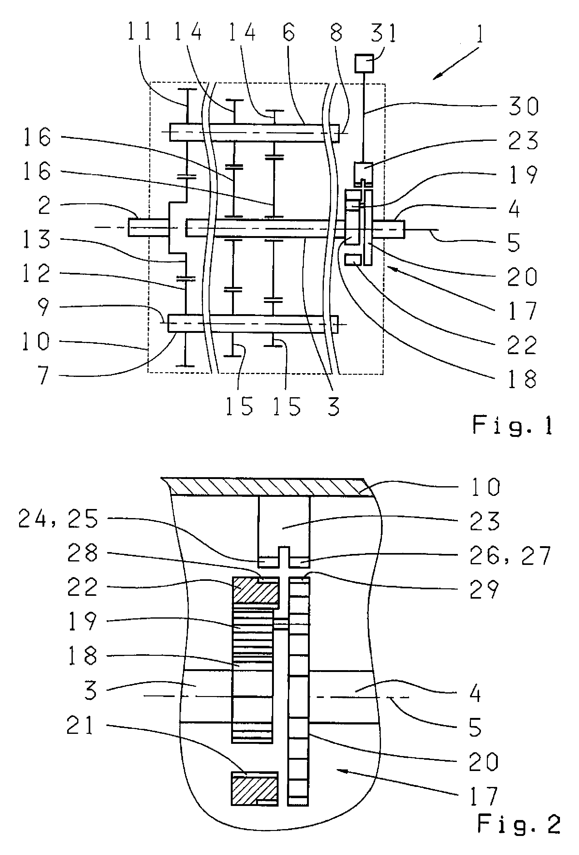
[0031]FIG. 1 is a schematic illustration of an embodiment of a transmission 1, which is operated based on the method. The transmission 1, which can be used in a motor vehicle, is a co-axial transmission comprising an input shaft 2, a main shaft 3 and an output shaft 4, which are disposed on an axle 5, one behind the other. Furthermore, two countershafts 6, 7 are provided, which extend along two axles 8, 9 disposed parallel to the axle 5. The main shaft 3 is floatingly supported between the two countershafts 6, 7 and with large axial play between the input shaft 2 and the output shaft 4. The transmission 1 furthermore comprises a transmission housing 10, through which the ends of the input and output shafts 2, 4, facing away from the main shaft 3, extend to the outside.

[0032]One input pinion 11, 12 is respectively attached on the countershafts 6, 7 which meshes with an output pinion 13 of the input shaft 2 so that the countershafts 6, 7 can be driven by the input shaft 2. In addition...


PUM


Abstract

The present invention relates to a method for determining the rotational speed of the main shaft (3) of a transmission in which the main shaft (3) is connected to an output shaft (4) via a shiftable planetary gear (17), whereby the main shaft (3) is connected in a rotationally fixed manner to the sun gear (18) and the output shaft (4) is connected in a rotationally fixed manner to the planet carrier (20). The steps of the method are picking up the rotational speed (nHohlrad) of the ring gear (22), picking up the rotational speed (nAbtrieb) of the output shaft or the planet carrier (20), and computing the rotational speed (nHauptwelle) of the main shaft (3) from the rotational speed (nHohlrad) of the ring gear and the rotational speed (nAbtrieb) of the output shaft or the planet carrier (20). The present invention further relates to a transmission having a rotational speed pickup device.

Description

[0001]This application is a national stage completion of PCT / EP2007 / 054017 filed Apr. 25, 2007, which claims priority from German Application Serial No. 10 2006 023 552.5 filed May 19, 2006.FIELD OF THE INVENTION[0002]The present invention relates to a method for determining the rotational speed of the main shaft of a transmission in which the main shaft is connected to an output shaft, via a shiftable planetary gear, where the main shaft is connected in a rotationally fixed manner to the sun gear and the output shaft is connected in a rotationally fixed manner to the planet carrier. The present invention further relates to a transmission having a rotational speed pickup device.BACKGROUND OF THE INVENTION[0003]Transmissions, which have rotational speed pickup devices for generating a speed signal for a motor vehicle or the like, are known from the state of the art. These rotational speed pickup devices basically include a signal or rotational speed transmitter that is connected in a...

Claims


Application Information

Patent Timeline
Patent Type & Authority Applications(United States)
IPC IPC(8): F16H57/08G01P3/18
CPCF16H59/38G01P3/60G01P3/48
Inventor FUHRER, KIMPUTH, THOMASGESSLER, FRANK
Owner ZF FRIEDRICHSHAFEN AG
Why Eureka
Try Eureka