Capsule-type medical apparatus, guidance system and guidance method therefor, and intrasubject insertion apparatus

Inactive Publication Date: 2009-11-12
OLYMPUS MEDICAL SYST CORP +1
View PDF54 Cites 47 Cited by
  • Summary
  • Abstract
  • Description
  • Claims
  • Application Information

AI Technical Summary

Benefits of technology

[0011]On the other hand, with the guidance system of the capsule-type medical apparatus described in Patent Document 1, since the rotational motion of the capsule is converted into propulsive motion in the direction of the longitudinal axis through the spiral ridge formed on the outer circumferential surface of the cylindrical capsule, the propulsion speed and the position of the capsule can be controlled precisely according to the lead of the spiral ridge by controlling the rotational speed of the capsule. In addition, the structure of the apparatus can be made simple because no gradient magnetic field is required as an external magnetic field but instead a magnetic field with uniform intensity is rotated.
[0042]Furthermore, since the intrasubject insertion apparatus according to the present invention obtains a stable propulsion force by ensuring an appropriate spiral shape of the spiral-structured portion, it is suitable for use in medical applications, such as examination, therapy, and treatment of a subject.

Problems solved by technology

The guidance system of the capsule-type medical apparatus described in Patent Document 2 is problematic in that the apparatus is complicated because a three-dimensional gradient magnetic field needs to be formed with high accuracy in order to appropriately guide the capsule-type medical apparatus in the body.
Furthermore, it is difficult to precisely control the speed and position of the capsule-type medical apparatus with a technique producing a propulsion force based on a gradient magnetic field.
However, the capsule-type medical apparatus described in Patent Document 1 has a disadvantage in that it is not possible to easily change the orientation thereof in a desired direction since it is designed to advance mainly in a direction of the longitudinal axis thereof.
For this reason, the above-described intracorporeal guiding device experiences poor contact between the membrane member and the wall in the lumen, which significantly decreases the propulsion force produced by the screwing operation.
On the other hand, in the above-described intracorporeal guiding device, when the inflation pressure of the membrane member becomes low, it is difficult to maintain the spiral shape, which also reduces the propulsion force produced by the screwing operation.

Method used


Image

  • Capsule-type medical apparatus, guidance system and guidance method therefor, and intrasubject insertion apparatus
  • Capsule-type medical apparatus, guidance system and guidance method therefor, and intrasubject insertion apparatus
  • Capsule-type medical apparatus, guidance system and guidance method therefor, and intrasubject insertion apparatus

Examples


first embodiment

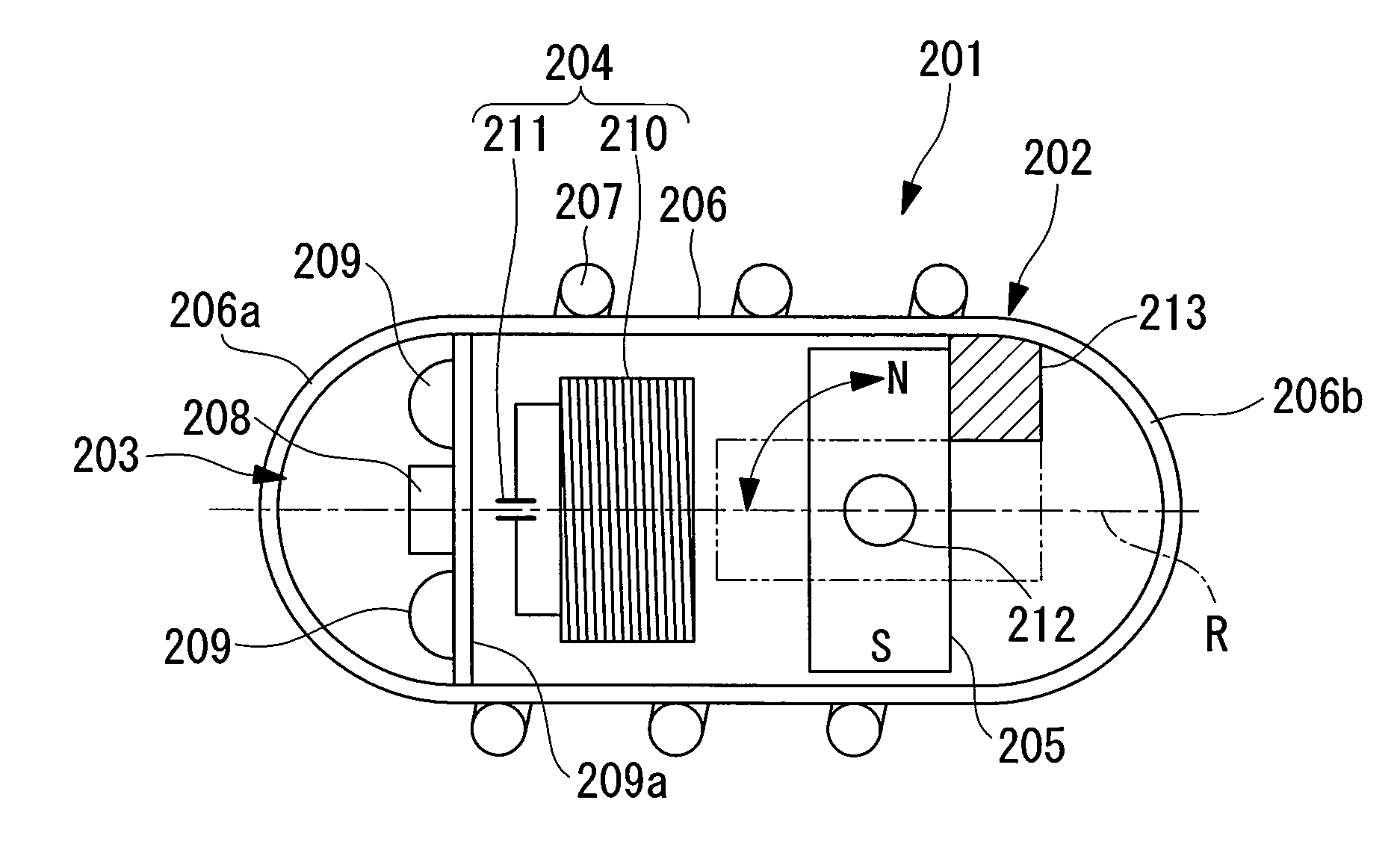
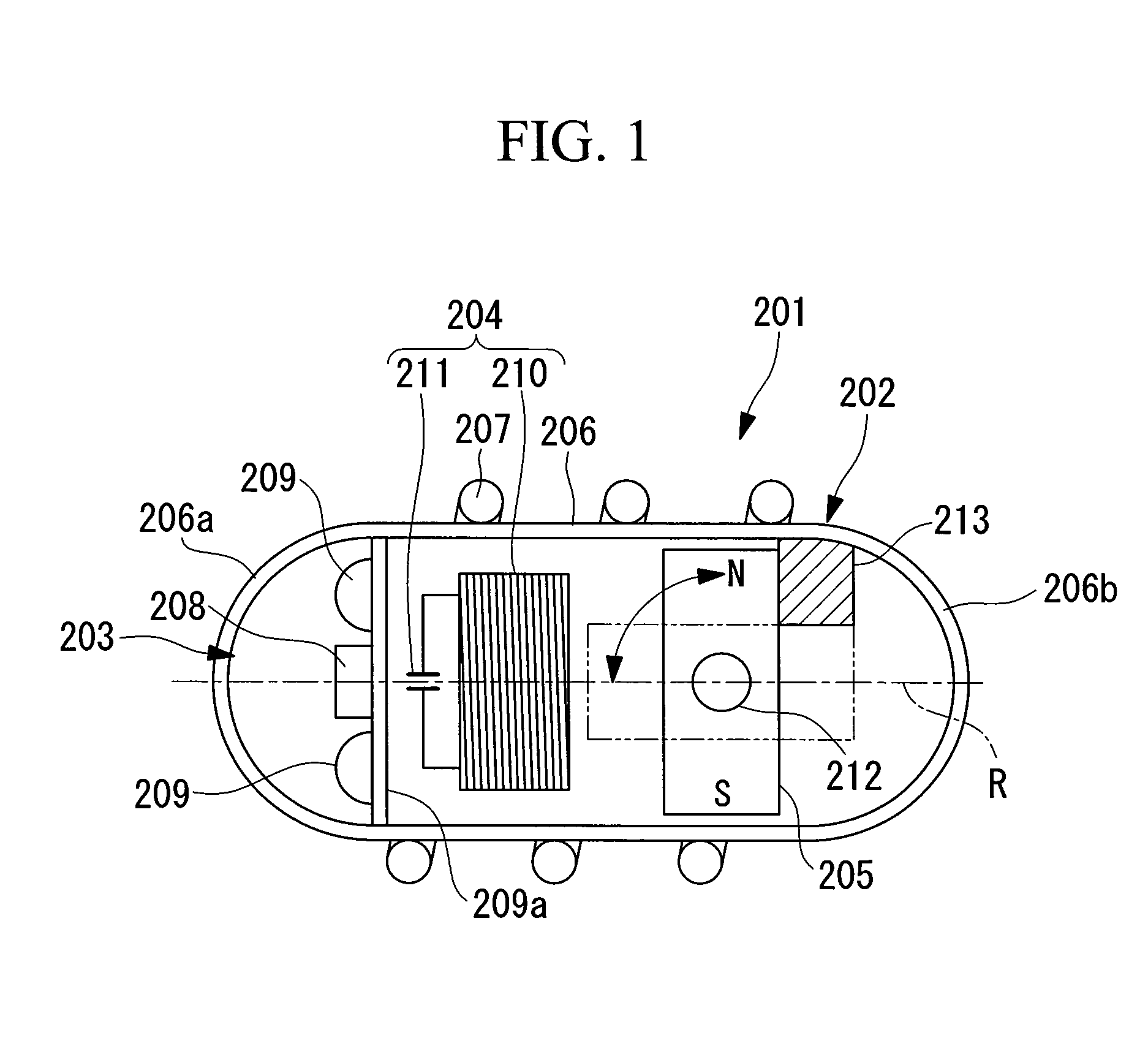
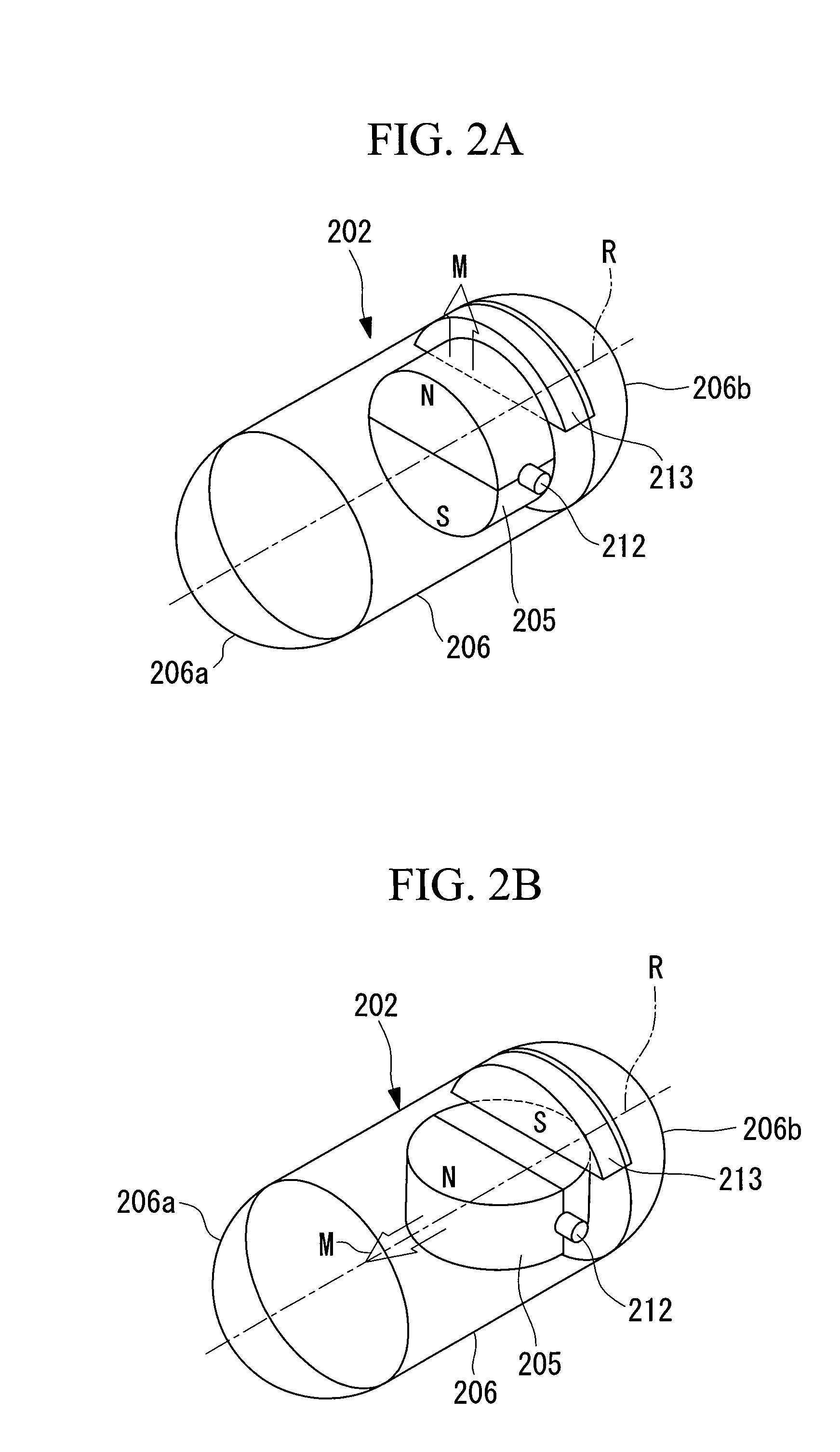
[0127]A capsule-type endoscope (capsule-type medical apparatus) 201 according to a first embodiment of the present invention will now be described with reference to FIG. 1, FIG. 2A, and FIG. 2B.

[0128]As shown in FIG. 1, the capsule-type endoscope 201 according to this embodiment includes a capsule 202; an imaging section 203 which is accommodated in the capsule 202 and captures an image of the internal surface of a passage in the body cavity of a subject; an induced-magnetic-field generating section 204; and a permanent magnet (magnet) 205.

[0129]The capsule 202 includes a cylindrical capsule main body 206 (hereinafter, referred to just as the main body) having a central axis aligned with a longitudinal axis R of the capsule-type endoscope 201; a transparent, hemispherical front-end portion 206a covering the front end of the main body 206; and a hemispherical rear-end portion 206b covering the rear end of the main body 206. The capsule 202 constitutes a capsule container that is seal...

second embodiment

[0196]Next, a capsule-type endoscope according to a second embodiment of the present invention will be described with reference to FIG. 15A to FIG. 15C.

[0197]As shown in FIG. 15A to FIG. 15C, a capsule-type endoscope 201′ according to this embodiment includes a fan-shaped permanent magnet 205′ having an arc-shaped portion 205c and a central angle of 90°; and a casing 218 accommodating the permanent magnet 205′.

[0198]The casing 218 includes wall surfaces 218a that are made of magnetic materials so as to hold by attraction the arc-shaped surface 205c of the permanent magnet 205′ and the two side surfaces having the arc-shaped portion 205c interposed therebetween; and a wall surface 218b made of another non-magnetic material.

[0199]The permanent magnet 205′ has one side surface magnetized as a north pole and has the arc-shaped portion magnetized as a south pole. As a result, as shown in FIG. 15A, while one side surface of the permanent magnet 205′ is held in contact with one wall surfac...

third embodiment

[0204]Next, a capsule-type endoscope 201″ according to a third embodiment of the present invention will be described with reference to FIG. 19A to FIG. 19C.

[0205]Unlike the capsule-type endoscopes 201 and 201′ according to the first and second embodiments where the guidance mode is switched by the external magnetic field M, the capsule-type endoscope 201″ according to this embodiment switches the guidance mode by a mechanical pressing force F, which is applied externally.

[0206]As shown in FIG. 19A, the capsule-type endoscope 201″ according to this embodiment includes a permanent magnet 205″ shaped like a rectangular parallelepiped; a pedestal 219 that holds by attraction the permanent magnet 205″; a lever 220 pivotably provided on the pedestal 219; and a pressing rod 221 that presses the permanent magnet 205″ off the pedestal 219 as a result of being pressed by the lever 220. Furthermore, the rear-end portion 206b of the capsule 202 is made of a flexible material and, therefore, is ...


PUM


Abstract

Using a guidance system with a simple configuration, propulsive motion along a longitudinal direction and changing of the propulsion direction are easily performed with good precision and stability. There is provided a capsule-type medical apparatus 201 which is inserted into the body of a subject and is guided by an external magnetic field, the capsule-type medical apparatus 201 comprising: a substantially cylindrical capsule 202; a propulsion mechanism 207 for converting rotary motion about a longitudinal axis R of the capsule 202 into propulsive motion along the longitudinal axis R; a magnet 205 accommodated inside the capsule 202 and disposed in such a manner that the magnetic-pole direction thereof can be switched between a direction along the longitudinal axis R and a direction intersecting the longitudinal axis R; and a securing portion 212 for securing the magnet 205 to the capsule 202 in each of the switched states of the magnetic-pole direction.

Description

TECHNICAL FIELD[0001]The present invention relates to a capsule-type medical apparatus, a guidance system and a guidance method therefor, and an intrasubject insertion apparatus which is inserted into a body cavity and advances while rotating.BACKGROUND ART[0002]Capsule-type medical apparatuses that have spiral ridges, extending along the longitudinal axes, formed on the outer circumferential surfaces of substantially cylindrical capsules thereof and that include, in the capsules, permanent magnets whose magnetic poles are aligned in a direction orthogonal to the longitudinal axes are well known (refer to, for example, Patent Document 1).[0003]In such a capsule-type medical apparatus, the capsule can be rotated about the longitudinal axis thereof by drawing upon the property that the permanent magnet therein rotates so as to align its magnetic-pole direction in the direction of an external magnetic field produced in a working space thereof when the external magnetic field is rotated...

Claims


Application Information

Patent Timeline
IPC IPC(8): A61B1/00
CPCA61B1/00082A61B1/00156A61B1/00158A61M31/002A61B5/073A61B2019/2253A61B5/7232A61B1/041A61B34/73A61B1/00148
Inventor TAKIZAWA, HIRONOBUKAWANO, HIRONAOUCHIYAMA, AKIOTANAKA, SHINSUKECHIBA, ATSUSHI
Owner OLYMPUS MEDICAL SYST CORP
Why Eureka
Try Eureka