
Dynamic stabilization assembly with frusto-conical connection

Inactive Publication Date: 2009-11-12
JACKSON
View PDF99 Cites 36 Cited by
  • Summary
  • Abstract
  • Description
  • Claims
  • Application Information

AI Technical Summary

Benefits of technology

[0007]An object of the invention is to provide dynamic medical implant stabilization assemblies having longitudinal connecting members that include a flexible portion that can resist shear forces and that can allow for controlled bending, torsion, compression and distraction of the assembly. A further object of the invention is to provide dynamic medical implant longitudinal connecting members that may be utilized with a variety of bone screws, hooks and other bone anchors. Another object of the invention is to provide a more rigid or solid connecting member portion or segment, if desired, such as a solid rod portion integral with the flexible portion. Additionally, it is an object of the invention to provide a lightweight, reduced volume, low profi

Problems solved by technology

Although flexible, the cords or strands utilized in such systems typically do not allow for elastic distraction of the system once implanted because the cord or strand must be stretched or pulled to maximum tension in order to provide a stable, supportive system.
Such tensioned cord and spacer systems may also cause facet joint compression during spinal movement, especially flexion.
The complex dynamic conditions associated with spinal movement create challenges for the design of elongate elastic longitudinal connecting members that exhibit an adequate fatigue strength to provide stabilization and protected motion of the spine, without fusion, and that allow for some natural movement of the portion of the spine being reinforced and supported by the elongate elastic or flexible connecting member.
A further challenge are situations in which a portion or length of the spine requires a more rigid stabilization, possibly including fusion, while another portion or length may be better supported by a more dynamic system that allows for protective movement.

Method used


Image

  • Dynamic stabilization assembly with frusto-conical connection
  • Dynamic stabilization assembly with frusto-conical connection
  • Dynamic stabilization assembly with frusto-conical connection

Examples


Embodiment Construction

[0070]As required, detailed embodiments of the present invention are disclosed herein; however, it is to be understood that the disclosed embodiments are merely exemplary of the invention, which may be embodied in various forms. Therefore, specific structural and functional details disclosed herein are not to be interpreted as limiting, but merely as a basis for the claims and as a representative basis for teaching one skilled in the art to variously employ the present invention in virtually any appropriately detailed structure. It is also noted that any reference to the words top, bottom, up and down, and the like, in this application refers to the alignment shown in the various drawings, as well as the normal connotations applied to such devices, and is not intended to restrict positioning of the connecting member assemblies of the application and cooperating bone anchors in actual use.

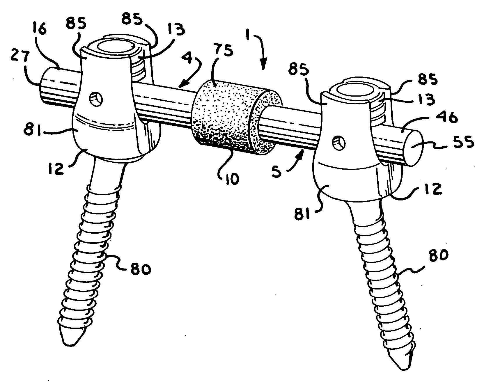
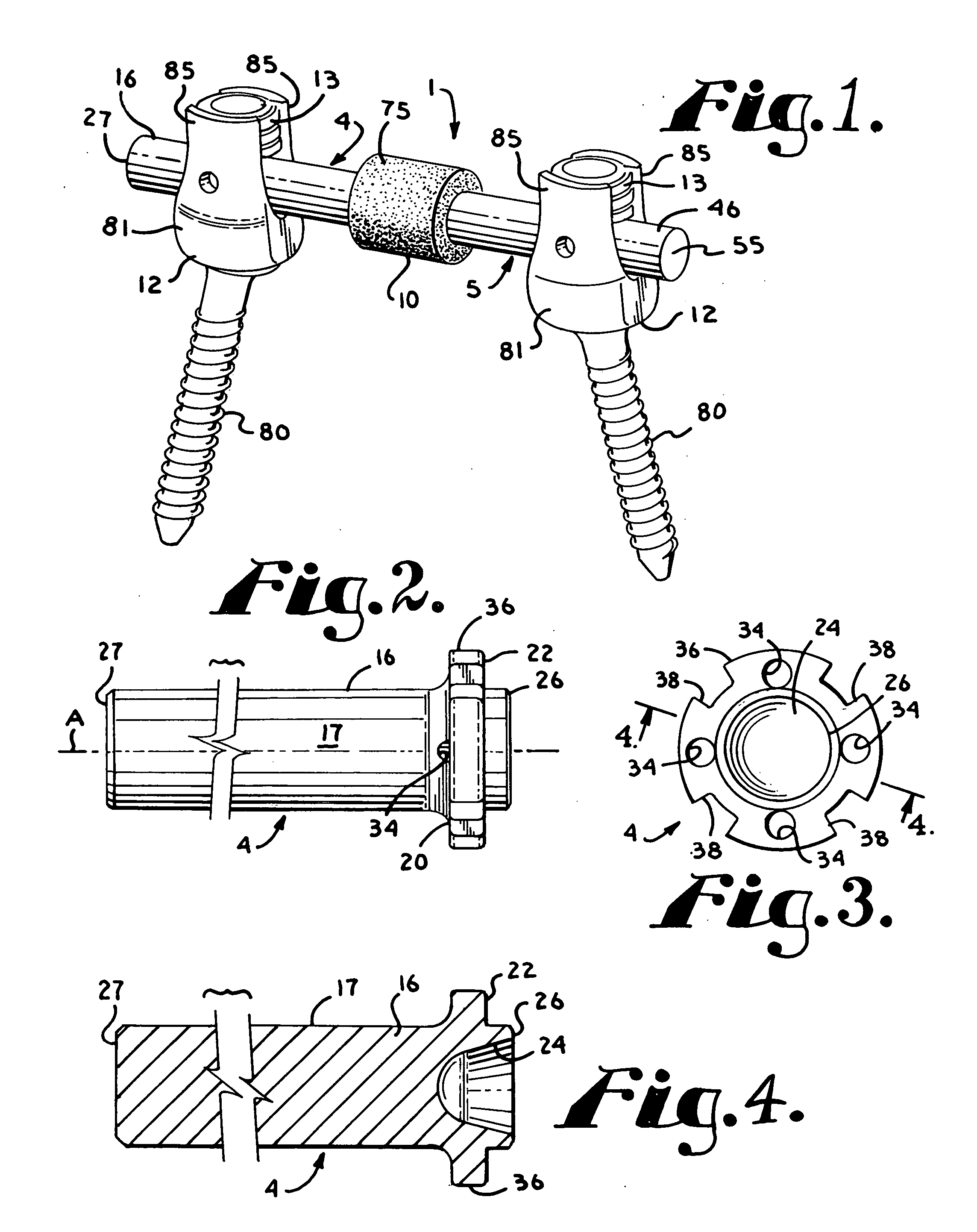
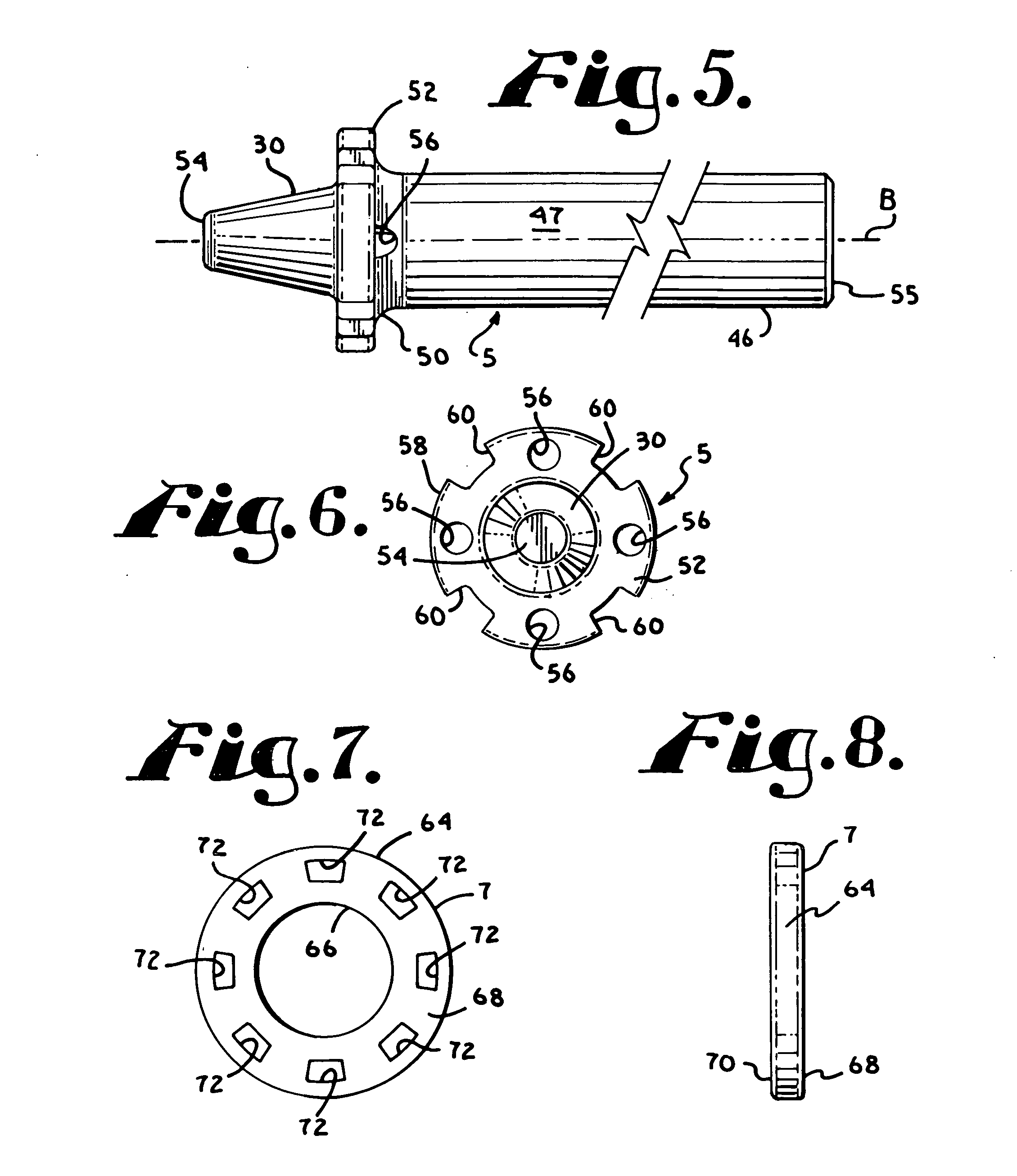
[0071]With reference to FIGS. 1-18, the reference numeral 1 generally designates a non-fusion dy...


PUM


Abstract

A dynamic fixation medical implant for attachment to at least two bone anchors includes a longitudinal connecting member assembly having first and second rigid sections, at least one section having a convex or frusto-conical surface held in spaced relation with the other section by an elastic spacer. The spacer may be an over-mold that connects the first and second rigid sections. Some embodiments include an inner, tougher spacer and a separate over-molded spacer.

Description

CROSS REFERENCE TO RELATED APPLICATIONS[0001]This application claims the benefit of U.S. Provisional Patent Application No. 61 / 132,911, filed Jun. 24, 2008, which is incorporated by reference herein. This application is also a continuation-in-part of U.S. patent application Ser. No. 12 / 069,577 filed Feb. 11, 2008 that claims the benefit of U.S. Provisional Patent Application Nos. 60 / 997,079 filed Oct. 1, 2007 and 60 / 900,816 filed Feb. 12, 2007, all of which are incorporated by reference herein. This application is also a continuation-in-part of U.S. patent application Ser. No. 12 / 070,535 filed Feb. 19, 2008 that claims the benefit of U.S. Provisional Patent Application No. 60 / 902,470 filed Feb. 21, 2007, both of which are incorporated by reference herein. This application is also a continuation-in-part of U.S. patent application Ser. No. 12 / 287,035 filed Oct. 3, 2008 that claims the benefit of U.S. Provisional Patent Application No. 60 / 999,965 filed Oct. 23, 2007, both of which are ...

Claims


Application Information

Patent Timeline
IPC IPC(8): A61B17/70A61B17/86
CPCA61B17/7004A61B17/7037A61B17/7031A61B17/7023
Inventor JACKSON, ROGER P.
Owner JACKSON
Features
  • Generate Ideas
  • Intellectual Property
  • Life Sciences
  • Materials
  • Tech Scout
  • Unparalleled Data Quality
  • Higher Quality Content
  • 60% Fewer Hallucinations
Learn More