Spiral-toothed gear

a technology of spiral-toothed gear and flange, which is applied in the direction of gearing, gearing elements, hoisting equipment, etc., can solve the problems of advantageously limited shape and position tolerances between the flange and the toothed ring, and achieve the effect of greatly minimizing the blind seams

Inactive Publication Date: 2009-11-19
ZF FRIEDRICHSHAFEN AG
View PDF16 Cites 26 Cited by
  • Summary
  • Abstract
  • Description
  • Claims
  • Application Information

AI Technical Summary

Benefits of technology

[0008]The recesses extending from both axial sides of the disk-shaped area into this area are preferably arranged such that the recesses originating from one axial outer side of the disk-shaped area are arranged offset in relation to those of the respective other axial outer side. In view of the most uniform distribution possible of the plastic on the outer circumference of the disk-shaped area and balanced material conditions relative to the geometry and the weight distribution, the recesses alternatingly extend into the disk-shaped area from one and the other axial outer side of the disk-shaped area. The recesses are, moreover, advantageously designed such that they expand towards the axial outer sides of the disk-shaped area in respect to their extension to the circumference. As was mentioned above, firm seating of the plastic toothed ring on the flange is achieved due to the design of the recesses, and there is at the same time advantageously a possibility of axial expansion during thermal loads.
[0009]According to an especially preferred variant of the spiral-toothed gear according to the present invention, the flange of the spiral-toothed gear is designed such that this flange is injected from the side for extrusion coating with the plastic. Corresponding to this variant, the axial outer surface of the disk-shaped area facing the hub has a circumferential, ring-shaped sprue channel under the recesses. Distributed over the circumference, a plurality of beads acting as injection points for the injection molding process are arranged in this sprue channel. To extrusion coat the flange, the plastic can thus be injected into a correspondingly shaped injection mold from this side, directed towards the beads. An especially uniform pressure distribution of the injected plastic mass within the sprue channel is achieved due to the beads. The cavity of the injection mold is filled through the sprue channel itself, as a result of which blind seams are advantageously greatly minimized. The finishing needed on the spiral-toothed gear removed from the injection mold is significantly reduced as a result.

Problems solved by technology

Due to the direct extrusion coating of the flange to prepare the toothed ring, the shape and position tolerances between the flange and the toothed ring are advantageously significantly limited.

Method used


Image

  • Spiral-toothed gear
  • Spiral-toothed gear
  • Spiral-toothed gear

Examples


Embodiment Construction

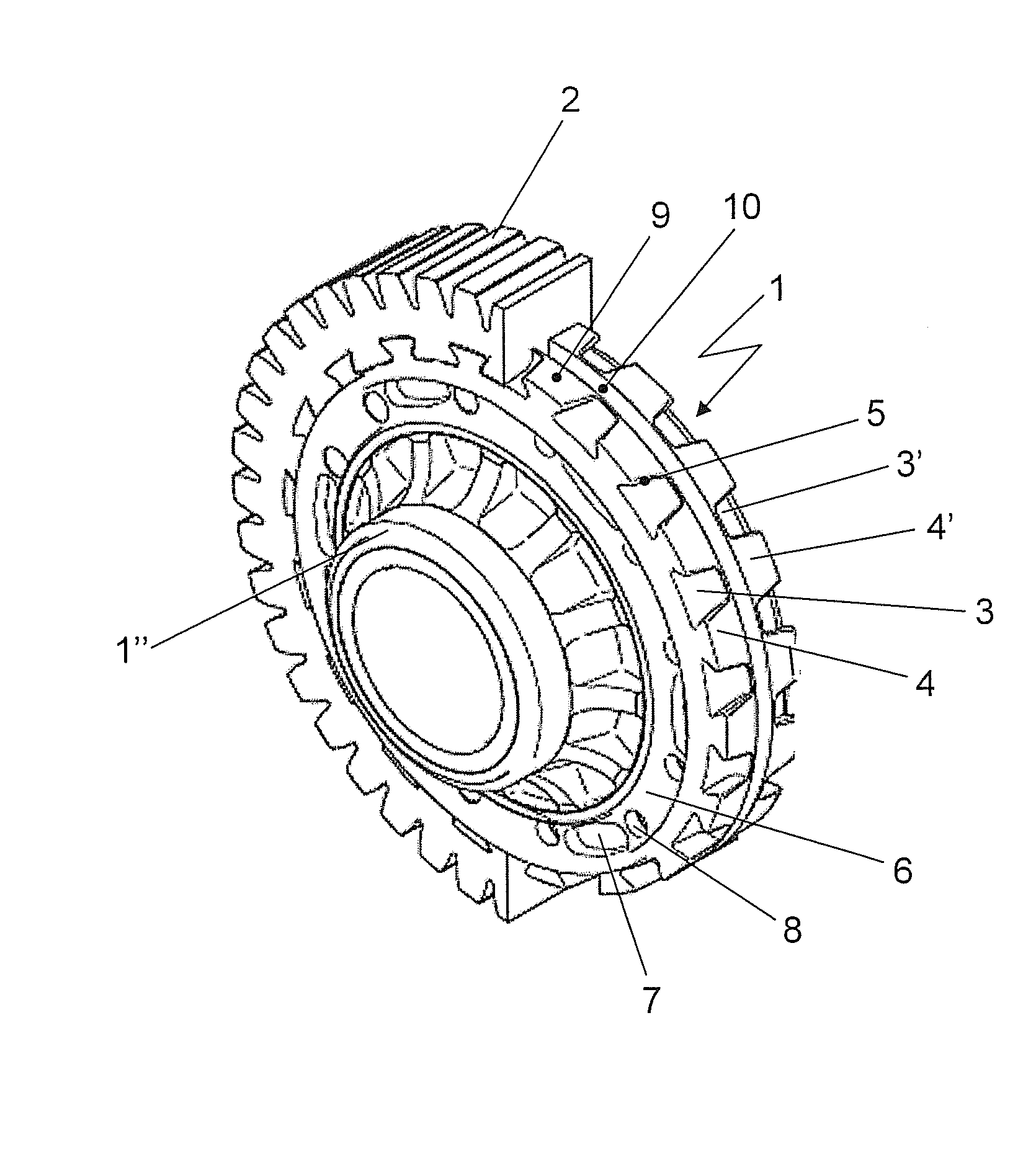
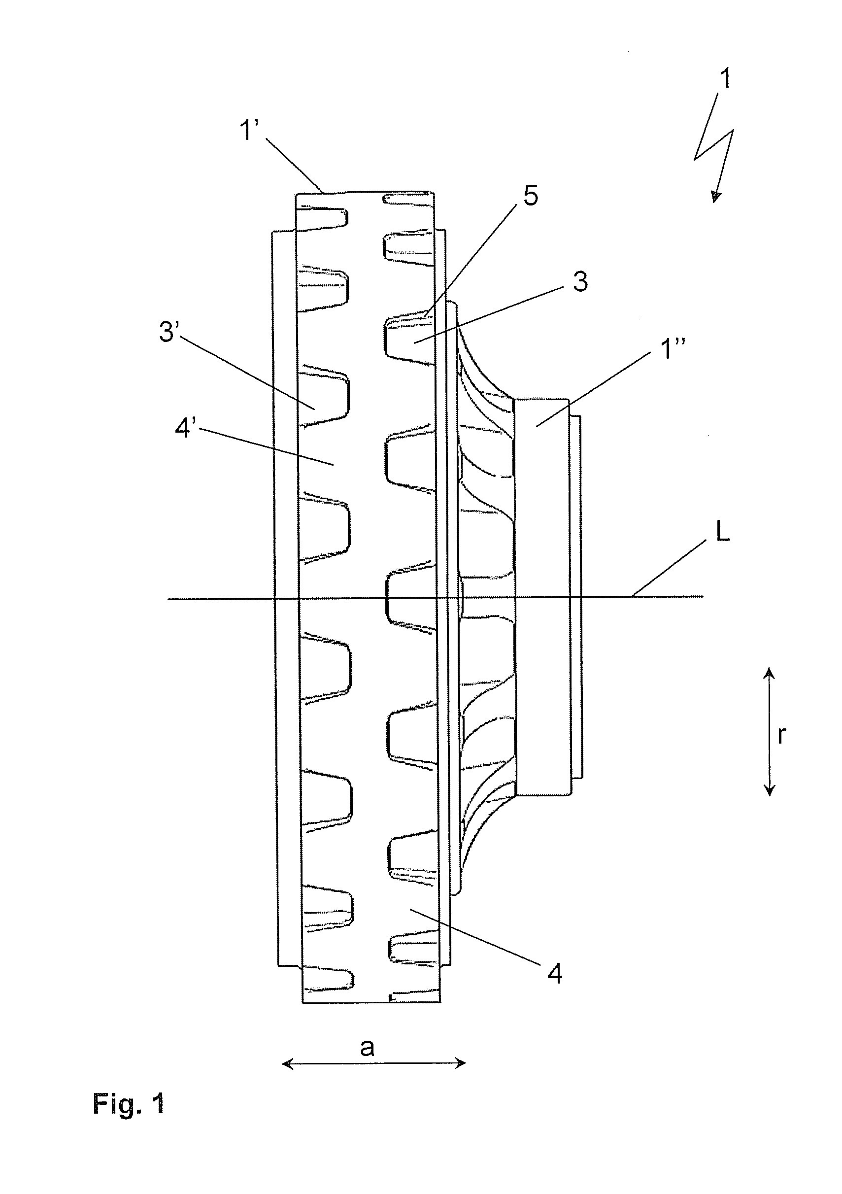
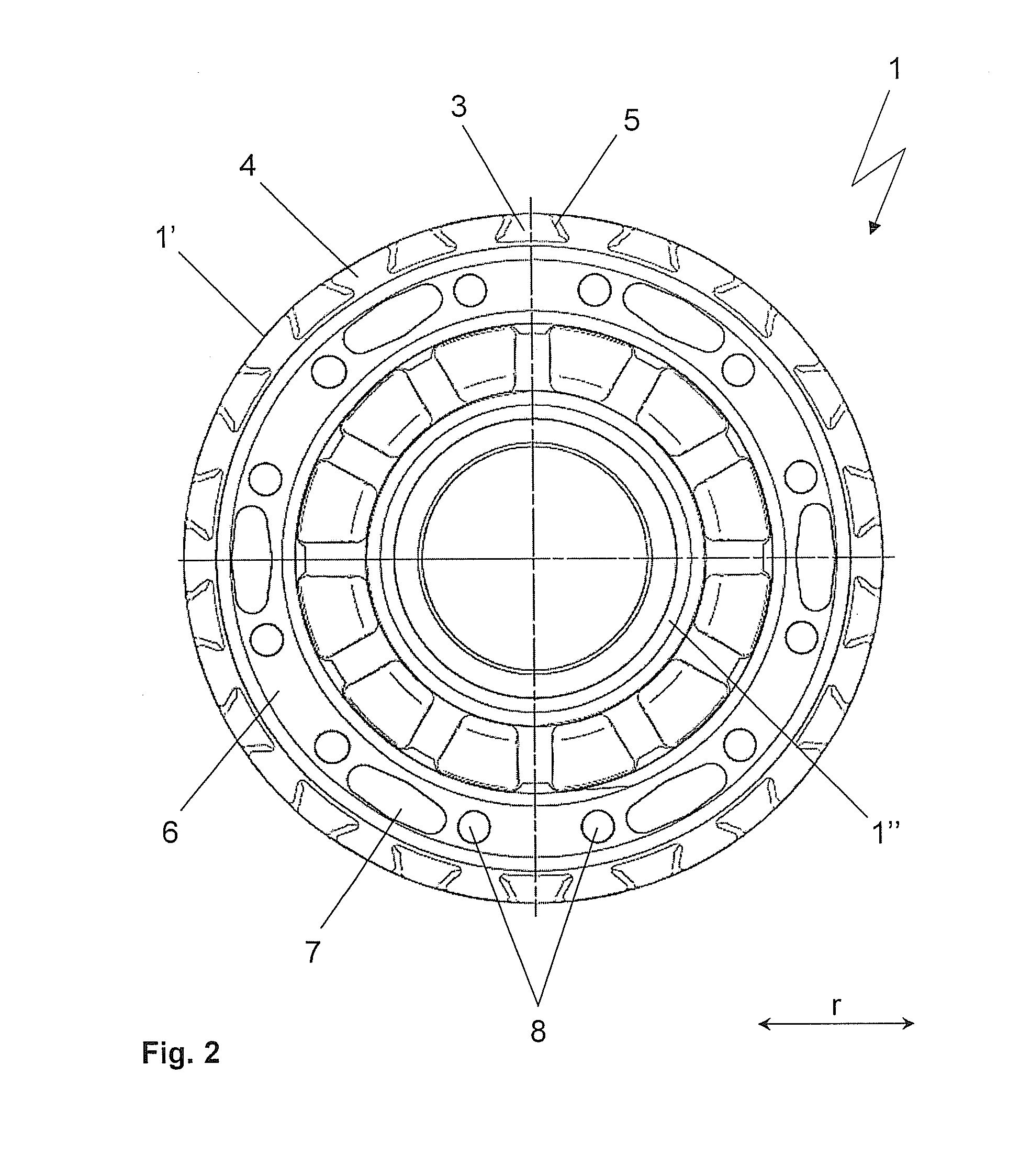
[0022]Referring to the drawings in particular, FIG. 1 shows the basic body 1 of a first embodiment of the spiral-toothed gear according to the present invention, which is not yet extrusion coated with plastic, in a top view from the radial direction r. As can be recognized, the basic body 1 is designed in the form of a flange. By extrusion coating flange 1, a circumferential plastic toothed ring 2 is later formed on the radial front surface of its disk-shaped area 1′. An area 1″ of reduced diameter, which forms the hub 1″ of the later spiral-toothed gear intended for being mounted on a shaft or the like in such way that it rotates in unison, is made integrally in one piece with the disk-shaped area 1′. As was stated above, flange 1 preferably consists of aluminum, but it may also be made of a glass fiber-reinforced plastic.

[0023]According to the basic idea of the present invention, a plurality of dovetail-shaped recesses 3, 3′, which are arranged distributed over the outer circumfer...


PUM


Abstract

A spiral-toothed gear is provided with a toothed ring (2) formed by extrusion coating a basic body (1) with a plastic. The spiral-toothed gear provides a connection between the basic body (1) and the toothed ring (2), whose strength makes possible the transmission of high torques in a reliable manner. The basic body (1) of the spiral-toothed gear has a flange with a disk-shaped area (1′) that is extrusion coated with the plastic toothed ring (2). The area (1″) of reduced diameter adjoining area (1′) forms a hub for mounting the spiral-toothed gear on a shaft in such a way that it rotates in unison. The area (1′) of the flange has, axially on both sides, a plurality of recesses (3, 3′) each, which are arranged distributed on its circumference, extend primarily in the axial direction but do not pass through area (1′). The recesses (3, 3′) are of a dovetail design, so that sections (4, 4′) of the outer circumference of area (1′), which are left in place between them, are undercut by the edges of the recesses (3, 3′), which said edges extend in the axial direction.

Description

CROSS REFERENCE TO RELATED APPLICATIONS[0001]This application is a United States National Phase application of International Application PCT / DE2007 / 001042 and claims the benefit of priority under 35 U.S.C. § 119 of German Patent Application DE 10 2006 030 097.1 filed Jun. 28, 2006, the entire contents of which are incorporated herein by reference.FIELD OF THE INVENTION[0002]The present invention pertains to a spiral-toothed gear, which is to be arranged as part of a transmission, rotating in unison on a shaft or the like. It pertains, in particular, to a spiral-toothed gear, the running surface of which, shaped in the form of a toothed ring, is formed by extrusion coating a basic body with a plastic.BACKGROUND OF THE INVENTION[0003]Even though gears and spiral-toothed gears made of metal have, in general, a higher mechanical strength than gears consisting of plastic, they often cause rather substantial running noises during their use in a transmission. It is therefore known that spi...

Claims


Application Information

Patent Timeline
Patent Type & Authority Applications(United States)
IPC IPC(8): F16H55/17
CPCF16H55/06Y10T74/19698F16H2055/065F16H55/17
Inventor ROGOWSKI, WALDEMARBLANKENSPECK, REMT
Owner ZF FRIEDRICHSHAFEN AG
Why Eureka
Try Eureka