
Composite piston for a motor vehicle transmission

a technology for transmissions and pistons, applied in the direction of piston rings, engine seals, engine components, etc., can solve the problems of reducing the mechanical load capacity of the sealing lip, and causing the piston to be clamped. , to achieve the effect of reducing the risk of the piston being clamped and reducing the possibility of eccentricity

Inactive Publication Date: 2009-11-19
DICHTUNGSTECHN G BRUSS
View PDF3 Cites 7 Cited by
  • Summary
  • Abstract
  • Description
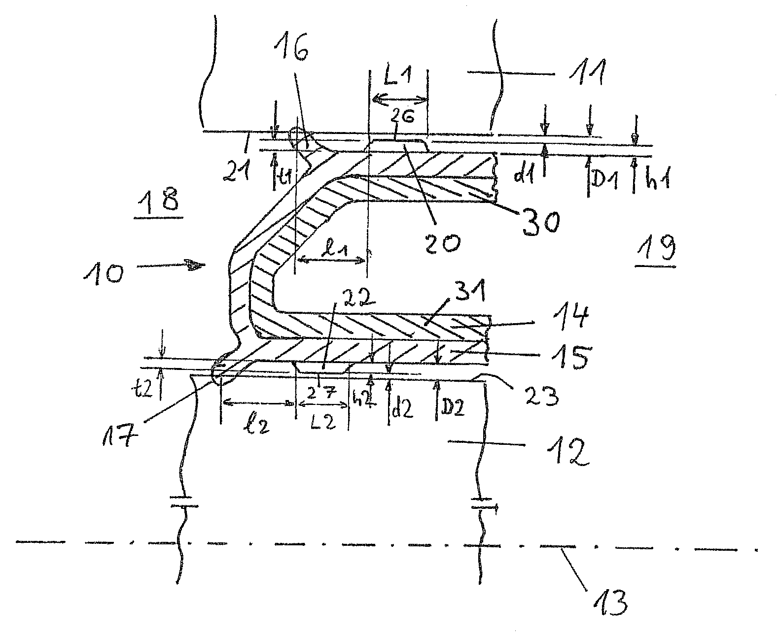
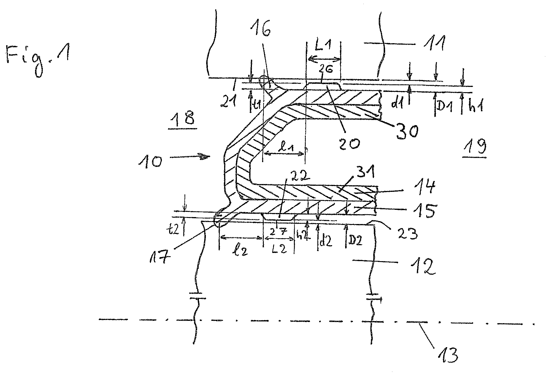
  • Claims
  • Application Information

AI Technical Summary

Benefits of technology

[0008]Embodiments of the invention provide a functionally reliable composite piston, in which an overload of the sealing lip as a result of an exceedingly large eccentricity of the piston is avoided.
[0009]Embodiments of the invention incorporate a support body; and at least one annular seal, wherein each of the at least one annular seal comprises: a sealing lip interacting in a sealing manner with a component forming a cylindrical sliding surface, wherein the composite piston can be displaced translationally relative to the component forming the cylindrical sliding surface; and an annular bead displaced axially relative to the sealing lip and arranged to have a distance d1 from the sliding surface in a non-loaded state, where d1 is greater than or equal to zero. Under radial load the annular bead comes in contact with the sliding surface and the sealing lip is mechanically relieved as a result of introducing forces into the sliding surface via the annular bead. Embodiments of the invention realizes a functional separation by completely uncoupling the sealing element from the guiding element: the annular bead serves for absorbing the radial forces generated by the piston and for introducing the same into the sliding surface so that the flexibility of the sealing lip is not affected adversely and the sealing function is therefore optimally guaranteed. Because of the annular bead according to the invention an optimal centering of the piston is therefore already realized during the assembly.
[0010]In pistons inserted into rotating components the annular bead helps to reduce an eccentricity due to the imbalance of the piston.
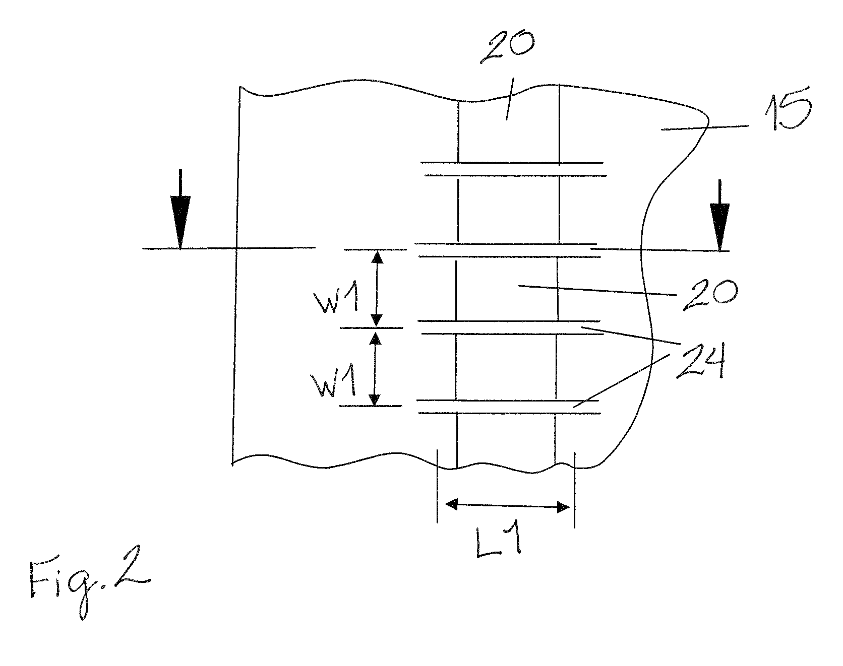
[0012]Advantageously, at least one axial gap, and preferably a plurality of axial gaps, in particular evenly distributed over its circumference, is provided in the annular bead. These allow oil to reach the seal also from the low pressure side in order to prevent the bead from obstructing the lubrication of the sealing lip. The gap further reduces the risk of the piston being clamped, since additional volume is provided to which the elastomer can pass for example upon excessive expansion.
[0013]The annular bead preferably is dimensioned in such a way that under pressure load a radial deformation occurs. Thereby, the annular bead comes in contact with the sliding surface earlier and the possible eccentricity of the piston is further reduced.

Problems solved by technology

An eccentric displacement can already occur when mounting such a piston, as the reset force of the sealing lips in particular in the pre-loaded state is not always sufficient for a complete centering of the piston.
In rotating applications the reset force of the sealing lips is not sufficient for compensating the occurring centrifugal forces so that the piston abuts on the sliding surface.
The eccentricity causes the sealing gap on one side to possibly increase to the twice, resulting in a severe reduction of the mechanical load capacity of the sealing lip.
The sealing lip may possibly break off in the event of overload so that the functioning of the piston is no longer guaranteed.
However, also in non-rotating applications it may possibly not be permissible that the weight of the piston is transmitted via the sealing lips if for example a non-permissible eccentricity would occur due to a heavy weight of the piston.

Method used


Image

  • Composite piston for a motor vehicle transmission
  • Composite piston for a motor vehicle transmission
  • Composite piston for a motor vehicle transmission

Examples


Embodiment Construction

[0019]Embodiments of the invention relate to a composite piston for a motor vehicle transmission comprising a support body and at least one annular seal connected thereto with an elastomer sealing lip. Such pneumatically or hydraulically actuated composite pistons are for example used in automatic vehicle transmissions, in particular for shifting multi-disc clutches or brake bands, as well as in hydraulically or pneumatically actuated servo mechanisms of motor vehicles.

[0020]The composite piston 10 shown in FIG. 1 can be displaced translationally along the central axis 13 between a cylinder 11 and a shaft 12. The composite piston has an annular form around the central axis 13 of the cylinder 11 and the shaft 12. The composite piston 10 includes an annular support body 14 having for example a U-profile, as can be seen from FIG. 1. The support body 14 can be made of metal, in particular of sheet steel, or of a plastic material. The composite piston 10 preferably consists of two compon...


PUM


Abstract

A composite piston (10) for a motor vehicle transmission comprises a support body (14) and at least one rotationally symmetric annular seal comprising an elastomer sealing lip (16, 17) interacting in a sealing manner with a component (11, 12) forming a cylindrical sliding surface (21, 23), wherein the composite piston (10) can be displaced translationally relative to the component (11, 12) forming the cylindrical sliding surface. The annular seal comprises an elastomer annular bead (20, 22) displaced axially relative to the sealing lip (16, 17), wherein the annular bead is arranged to have a distance d1, d2 from the sliding surface (21, 23) in the non-loaded state larger than or equal to zero.

Description

RELATED APPLICATION[0001]The application claims priority under 35 U.S.C. §119(e) of German Patent Application No. DE 102008024163.6, filed on May 19, 2008, which is hereby incorporated by reference in its entirety.BACKGROUND OF INVENTION[0002]Composite pistons for a motor vehicle transmission are known from DE 199 15 022 B4 and DE 202 09 125 U1. The pressure portion occurring at the annular gap is transmitted to the piston via the annular seals as an axial force. This axial force needs to be supported by the piston in a suitable manner, where the mechanical load capacity of an elastomer seal might be exceeded at common pressures unless the constructional configuration is very accurate. An eccentric displacement can already occur when mounting such a piston, as the reset force of the sealing lips in particular in the pre-loaded state is not always sufficient for a complete centering of the piston.[0003]In rotating applications the reset force of the sealing lips is not sufficient for...

Claims


Application Information

Patent Timeline
IPC IPC(8): F16J9/00
CPCF16J15/3236F16J15/3224
Inventor SCHMIDT, HENNING
Owner DICHTUNGSTECHN G BRUSS
Learn More